New Ashida "Neo" Build - Need Help!

Joined
Jun 26, 2026
Messages
10
Likes
11
Hi all!

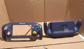
Starting a thread as I build my first-time portable. Fell in love with the Ashida but somewhere along the way I opted for the AliExpress components pathway (I think it came down to budget and getting a case I liked at a good price point). I've read all the 4Layer/Wesk guides, including full GingerofOz/Dubesintheshower videos and got a general idea of how components come together, but obviously the AliExpress components changes all that. I've been talking with them to get help but wanted to start a thread here as another resource for my questions.

Where I'm at: Need to clear coat my shell then that will be done, finished softmodding the wii, ready for the omgwtf trim.

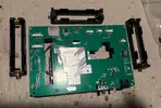
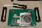
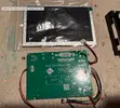
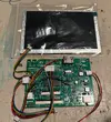
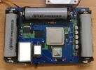
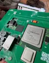
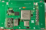
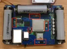
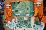
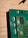
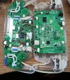
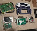
Anyway, below are roughly all the components I've sourced from the AliExpress store and I need help starting to get an idea of how these pieces are connected. I mostly am trying to figure out if the battery holders get directly soldered to the power board, and then how the wii board will get connected to the power board such that I'll be able to confirm the wii board works post-trim.

Thanks everyone! Wish me luck, and excited to work with you all!
 

Attachments

  • All components.webp
    All components.webp
    608 KB · Views: 4
  • Power board A.webp
    Power board A.webp
    361.2 KB · Views: 4
  • Power board B.webp
    Power board B.webp
    412.4 KB · Views: 4
  • Screen:Driver A.webp
    Screen:Driver A.webp
    496 KB · Views: 6
  • Screen:Driver B.webp
    Screen:Driver B.webp
    468.9 KB · Views: 5
Hello and welcome!

It sounds like you're off to a really good start so far! It's worth noting that the Aliexpress Ashida doesn't seem to have too many (if any) worklogs on the forums (if there are any, I haven't come across them). This does imply we probably lack some documentation for this build, so there may be some things you end up having to figure out on your own. Having said that, the information found in the Wii trimming guide will still be very relevant as will information found in other people's worklogs here on the forums. I would definitely recommend checking out some user threads and the Wii trimming guide that I linked if you haven't already. I also made a Wii micro soldering guide which you can find here. It has great information, tools, and advice on performing the more challenging parts of these Wii mods.

To answer your question about the battery holders, they appear to solder straight to the PCB like this:
1784153554491.webp


As for the Wii, it looks like there's a designated spot for it once it gets trimmed, it looks like the screw holes line up here:

1784153729339.webp


I'm looking forward to seeing this worklog come together! It'll be another great resource for the community given that we don't have too many worklogs on this variation of Ashida and whatnot. Please remember you can always ask the community if you have a question, need advice, or get stuck on something.

Good luck!
 
What controller PCB is that? The only ones I've seen for sale are the black 4layertech ones and the green ones on aliexpress
 
What controller PCB is that? The only ones I've seen for sale are the black 4layertech ones and the green ones on aliexpress
It’s what I got off the aliexpress store, I assume it’s identical just a different color ‍♂️
 
  • Like
Reactions: cy
Hello and welcome!

It sounds like you're off to a really good start so far! It's worth noting that the Aliexpress Ashida doesn't seem to have too many (if any) worklogs on the forums (if there are any, I haven't come across them). This does imply we probably lack some documentation for this build, so there may be some things you end up having to figure out on your own. Having said that, the information found in the Wii trimming guide will still be very relevant as will information found in other people's worklogs here on the forums. I would definitely recommend checking out some user threads and the Wii trimming guide that I linked if you haven't already. I also made a Wii micro soldering guide which you can find here. It has great information, tools, and advice on performing the more challenging parts of these Wii mods.

To answer your question about the battery holders, they appear to solder straight to the PCB like this:
View attachment 43922

As for the Wii, it looks like there's a designated spot for it once it gets trimmed, it looks like the screw holes line up here:

View attachment 43923

I'm looking forward to seeing this worklog come together! It'll be another great resource for the community given that we don't have too many worklogs on this variation of Ashida and whatnot. Please remember you can always ask the community if you have a question, need advice, or get stuck on something.

Good luck!
Thanks so much!
 
Sorry forgot to also ask for advice on where to buy batteries? I saw on other posts generally to avoid aliexpress but mine calls for 18650 but there are different versions within that so any advice?
 
  • Like
Reactions: cy
Sorry forgot to also ask for advice on where to buy batteries? I saw on other posts generally to avoid aliexpress but mine calls for 18650 but there are different versions within that so any advice?
Most people I know get Samsung 18650s from MABD Electronics, but their Samsung batteries are out of stock as of right now. The Samsung ones they sell only go up to 3500 mAh which means they'll give you less battery life. I would recommend finding some cells that go up to 4000 mAh or even higher if they're available. I'm haven't bought any of these batteries myself yet, so I'm not sure where you can get them. I believe @YveltalGriffin knows where to find the highest capacity 18650 cells available so maybe ask him.
 
Here are the best cylindrical lithium-ion cells for portablizing applications, as of July 2026. All purchase links are from reputable online stores.
  • Amprius SA110 (4000mAh 18650):
https://diy500amp.com/products/amprius-sa110-18650-battery-cell-4000mah-ultra-high-capacity
  • Vapcell N41 (4050mAh 18650):
https://liionwholesale.com/products/vapcell-n41-18650-10a-flat-top-4050mah-battery-genuine
  • Linkdata 65P (6500mAh 21700):
https://diy500amp.com/products/link...ell-6500mah-52a-high-capacity-high-power-cell
  • BAK 65E (6500mAh 21700):
https://convoylight.com/products/bak-n21700cx-65e-21700-lithium-battery-6500mah-max-output-19a
  • Vapcell F66 (6600mAh 21700):
https://www.vapcelltech.com/h-pd-329.html

Please check out this post for details about actual battery discharge curves.

TL;DR, all advertised mAh values are from discharging the cell down to 2.50V. Depending on your regulators and battery management system, the real usable capacity will be lower.
 
I'm a simple man.. i see trimmed heatsink, i like.
 
  • Like
Reactions: cy
I’ve looked into this kit, but I can’t find the firmware for the RTD2660H they’re using. The one they use supports YPbPr and audio. The only YPbPr-compatible display I’ve been able to find is the 5-inch one from Eyoyo. I have all the other components (the power board and NGC controller kit), along with the schematics, and I’ve built it myself—the cost was less than 50 RMB.
 
  • Like
Reactions: cy
Hi all! Had a question/update: I'm about to trim the wii board, but trying to first get as best of an understanding possible with it's requirements, and I've been combing through the trim guide and videos, I've been able to figure out I won't need to relocate u10 with my board which is cool, and the board also has some nice placements with the other regulators making it a seemingly straightforward board-board install, but I'm getting stuck on understanding a couple things. The board pictured is the example from the seller's page, and you can see how they've wired the custom regulators but 1.8v is labeled GND and I don't otherwise see a GND wire. Also, I've see videos where they only solder a wire to one end of the regulator and in this case they've made connections on both ends for some of the regulators, does that matter? Thanks in advance for your help!

Fun part: Shell is done!
 

Attachments

  • Screenshot 2026-07-18 at 7.42.22 PM.webp
    Screenshot 2026-07-18 at 7.42.22 PM.webp
    726.7 KB · Views: 8
  • Screenshot 2026-07-18 at 7.15.20 PM.webp
    Screenshot 2026-07-18 at 7.15.20 PM.webp
    282.8 KB · Views: 3
Okay slight update to my last question regarding the 1.8v vs. GND: Ohkin told me "1.8v does not require a connection. 1v, 1.15v, 3.3v, these three voltages are enough for the Wii to work" so it looks like the GND really does utilizez the 1.8v pathway does that sound feasible? I feel like I'm getting to the point where I should just full send and copy exactly how he has things soldered rather than trying to understand it all, pre-assembly. Thanks all!
 
Okay slight update to my last question regarding the 1.8v vs. GND: Ohkin told me "1.8v does not require a connection. 1v, 1.15v, 3.3v, these three voltages are enough for the Wii to work" so it looks like the GND really does utilizez the 1.8v pathway does that sound feasible? I feel like I'm getting to the point where I should just full send and copy exactly how he has things soldered rather than trying to understand it all, pre-assembly. Thanks all!
Yeah that's fine. Every tantalum capacitor (the big black/orange ones) has one end connected to voltage and one end to GND. You can connect to just the GND end without issue. He probably did it that way so the solder joints would hold the all-in-one PCB against the Wii securely.
I’ve looked into this kit, but I can’t find the firmware for the RTD2660H they’re using. The one they use supports YPbPr and audio. The only YPbPr-compatible display I’ve been able to find is the 5-inch one from Eyoyo. I have all the other components (the power board and NGC controller kit), along with the schematics, and I’ve built it myself—the cost was less than 50 RMB.
You probably never will find it. Firmware licencing for those chips is heavily controlled. You have to sign contracts to be given the binaries and tools to write RTD firmware, and you will be sued if you are caught letting it out into the wild.
 
Hi all! Had a question/update: I'm about to trim the wii board, but trying to first get as best of an understanding possible with it's requirements, and I've been combing through the trim guide and videos, I've been able to figure out I won't need to relocate u10 with my board which is cool, and the board also has some nice placements with the other regulators making it a seemingly straightforward board-board install, but I'm getting stuck on understanding a couple things. The board pictured is the example from the seller's page, and you can see how they've wired the custom regulators but 1.8v is labeled GND and I don't otherwise see a GND wire. Also, I've see videos where they only solder a wire to one end of the regulator and in this case they've made connections on both ends for some of the regulators, does that matter? Thanks in advance for your help!

Fun part: Shell is done!
I forgot to comment on this when I first saw it. That shell looks absolutely beautiful! The GameCube stickers are such a nice touch!
 
Hey all!

Things have been progressing well: I'm just about done reverse engineering all the solder points to the point where I can at least test the wii board, the trim is done and I confirmed the resistances based on the guide - so far so good!

Right now I'm just practicing basic soldering on the scrap wii boards, but I was hoping for some input on how to pull off the soldering: Based on Ohkin's pics, it looks like his pcb is directly soldered to the wii's voltage points, but when I dry fit my wii board to the pcb, there's still about 1mm between each board. I'm wondering if I were to just solder across that space does anyone foresee any issues with that? I'm curious if anyone has suggestions on how to do this as simply/cleanly as possible without gobbing it with a ton of solder and potentially introducing shorts. Thanks all!
 

Attachments

  • Screenshot 2026-08-02 at 3.36.06 PM.webp
    Screenshot 2026-08-02 at 3.36.06 PM.webp
    512.9 KB · Views: 1
  • Screenshot 2026-08-02 at 3.35.47 PM.webp
    Screenshot 2026-08-02 at 3.35.47 PM.webp
    596.3 KB · Views: 1
  • Screenshot 2026-07-18 at 7.15.20 PM.webp
    Screenshot 2026-07-18 at 7.15.20 PM.webp
    259.1 KB · Views: 2
Hey all!

Things have been progressing well: I'm just about done reverse engineering all the solder points to the point where I can at least test the wii board, the trim is done and I confirmed the resistances based on the guide - so far so good!

Right now I'm just practicing basic soldering on the scrap wii boards, but I was hoping for some input on how to pull off the soldering: Based on Ohkin's pics, it looks like his pcb is directly soldered to the wii's voltage points, but when I dry fit my wii board to the pcb, there's still about 1mm between each board. I'm wondering if I were to just solder across that space does anyone foresee any issues with that? I'm curious if anyone has suggestions on how to do this as simply/cleanly as possible without gobbing it with a ton of solder and potentially introducing shorts. Thanks all!
I'd prob suggest using some component lead clippings (like from through-hole resistors and such) to bridge those gaps. It'll make it much easier for you and provide a stronger mechanical connection for the solder, preventing cracked joints later :)

I personally save mine for special occasions like this lol
b3462cfb-d446-4386-968b-0c783f55b4f2.webp
 
Hello everyone!

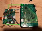
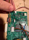
It's been a while and I'm here with my semi-regular roadblock/troubleshoot post. Updates since the last post: wii board is successfully (I think based on testing the resistances and continuity using a multimeter) soldered to the power board (3.3, 1.15, 1, gnd, and u10- used a 36 gauge magnet wire for that), so my thought on next step was to do a test boot to see if the wii board survived. re-connected the gpu/cpu heat sink and fan to the wii/pwr board, and then connected all that to the driver board which was then connected to the screen. Batteries installed, turned on: nothing. I then unplugged the driver board from the wii/pwr board, turned it on and got the power light and cpu/gpu fan to run which was cool.

Using a stepwise approach I re-connected one at a time the driver board back to the wii/pwr boards and found there was one specific connection it didn't like; I would get the power light and fan to run with all connections until I connected the one I labeled in red. I'm kind of at a point in the build where I don't know what exactly connecting things to but just going off of the reference pictures, which aren't exact but close enough (the one with the orange shell) I got off the seller's page so any insight would be amazing.

*as a P.S.: In my driver-wii/pwr board picture, the bottom green connect has a glare where you can't see what the label is, but it's PBGYGPRG
 

Attachments

  • Driver to wii:pwr board.webp
    Driver to wii:pwr board.webp
    631.5 KB · Views: 1
  • Driver up close.webp
    Driver up close.webp
    721 KB · Views: 1
  • Seller reference.webp
    Seller reference.webp
    537.3 KB · Views: 1
  • wii:pwr up close.webp
    wii:pwr up close.webp
    626.4 KB · Views: 1
Actually sorry I just found a more updated reference pic. Looks like the red connection isn't actually meant for the driver board but rather the controller pcb, but regardless I don't get any response from the screen when I power it all on. So far, I was at least able to confirm that adequate power is being sent to the driver board but nothing else has been done diagnostically.
 

Attachments

  • Screenshot 2026-08-16 at 11.17.49 AM.webp
    Screenshot 2026-08-16 at 11.17.49 AM.webp
    475.7 KB · Views: 1
Back
Top