Question GC+2.0 on Louii build not working, need help

Joined
May 28, 2025
Messages
8
Likes
4
Hey guys, I am building a Louii for my son for his birthday. This is my first portable so I apologize in advance for my ignorance. The soft mod and trim went well and tested with no issues. I am using a PMS PD3, RVL-PMS-2, U-Amp 2, RVL-DD and finally…..the GC+2.0. That is where I have hit a wall.

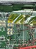
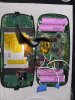
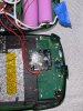
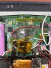
I cannot get the controller to work, there is no response. The system boots quickly and the RVLoader loads into the GC view. I have measured the resistance across the resistor array and am getting 758 ohms. I have good continuity from the GC board, through the wire, through both via’s and to the resistor. I have connected the data line to both via’s with the same result. One thing to note is that when I connect the data line to the GC board and measure from the pad on the GC board to the 3.3v side of the resistor I get 462 ohms. I am using the U10 emulator from the PMS-2 and have 3.27 volts at the via on the Wii. The wire for the data line is 34 gauge magnet wire. Power and ground are coming from the Wii board to through stranded 28 gauge wire.

I have attached pictures. Please forgive the wiring mess, it started nice until troubleshooting began, then nice went out the window. I appreciate any advice or tips that anyone can provide. Thank you.
 

Attachments

  • IMG_9402.jpeg
    IMG_9402.jpeg
    1.6 MB · Views: 106
  • IMG_9400.jpeg
    IMG_9400.jpeg
    2.1 MB · Views: 110
  • IMG_9399.jpeg
    IMG_9399.jpeg
    1.7 MB · Views: 94
  • IMG_9398.jpeg
    IMG_9398.jpeg
    2 MB · Views: 86
Hi Jscnell!
It's kinda hard to see from the picture, but I think you didn't plug the GC+ 2.0 to the correct via on the Wii motherboard.
If you refer to this picture on the definitive Wii Trimming Guide, you can see that your GC+ is wired to Controller 2, which cannot be used in the RVLoader's menus!
1748704329354.png

Also, your solder seems to be a bit too big, it might make shorts between some surrounding vias. Try to resolder your wire on the correct via with a little less solder. Don't forget to clean the solder up with isopropyl alcohol ;)

Hope this helps! Have a nice day!
 
It kinda looks like you shorted two channels to me (which would cause the lower resistance)
 
Hey guys, thank you both for looking at this and for your input. When I get back to my bench on Monday I will take a look and follow up. Have a good weekend.
 
Okay, got a chance to look at this today. The pictures were not very good last time but I did have the correct via for channel one (new picture attached for a sanity check). I cleaned the board up a bit and retook some measurements.

None of the channels are shorted together. I disconnected the data wire from the GC board. When I measure through the wire to the back side of the resistor grid I get 758 ohms. Then I reconnected the wire. When I measure from the data pad on the GC to the back side of the resistor grid on the wii with the wire connected, I get 400 ohms. Not sure what it should be with the data line connected but that seems like a sizable drop in resistance.

I reflowed the ground and 3.3v connections to the GC and tested all the pads to ensure they were not shorted to each other or to ground. Is there a way to test if the GC or wii are sending data? This is a two way data connection I am assuming?

Any other thoughts or ideas would be greatly appreciated.
 

Attachments

  • IMG_9540.jpeg
    IMG_9540.jpeg
    1.4 MB · Views: 97
I don't believe this is a two way connection, though I could be wrong. I believe the only thing sending anything is the controller sending inputs to the data pin on the Wii. If you have a oscilloscope, you could always check if there's any change of voltage that looks like data being sent. I'm not entirely sure how to check for certain, as I've never had issues with it. Have you checked from the data pin on the GC+ 2 to the pin on RA1? If it does have continuity, maybe the connection isn't always secure. Try scraping the via using an x-acto knife or fine tweezers if you haven't already. It can expose more copper, and help get a much better connection.
 
Hey JamesPi, thank you for taking a look. Yes, I do have continuity from the data pin on the GC to RA1.
 
It kinda looks like you shorted two channels to me (which would cause the lower resistance)
Hey Aurelio, thank you for taking a look. It was pretty messy but no, they were not shorted together. It seems I am getting some sort of resistance path to 3.3v through the GC2.0. It looks like that board is your design if I am reading correctly. If that is the case, first nice work! Second, what kind of resistance should I expect from the 3.3v side of RA1 on the wii to the d pad on the GC? I am assuming the GC2.0 can run standalone and does not need any special connection to the wii (like an ic2) other than the data line, is that correct? Does RVLoader need any files that I may have missed installing to recognize the GC controller inputs? Thank you in advance for any help.
 
Hey Aurelio, thank you for taking a look. It was pretty messy but no, they were not shorted together. It seems I am getting some sort of resistance path to 3.3v through the GC2.0. It looks like that board is your design if I am reading correctly. If that is the case, first nice work! Second, what kind of resistance should I expect from the 3.3v side of RA1 on the wii to the d pad on the GC? I am assuming the GC2.0 can run standalone and does not need any special connection to the wii (like an ic2) other than the data line, is that correct? Does RVLoader need any files that I may have missed installing to recognize the GC controller inputs? Thank you in advance for any help.
No extra files are required. GC+ requires the data line and GND to be the same as the wii (plus of course 3.3V power as well). The resistance should be around 700 Ohms
 
No extra files are required. GC+ requires the data line and GND to be the same as the wii (plus of course 3.3V power as well). The resistance should be around 700 Ohms
Okay, thank you. I am getting 421 ohms with the data wire connected to the GC. I have 758 without the wire connected to the GC. I have gone through my wiring and I don’t see any places where the 3.3v is shorted to ground but it seems that I don’t have enough resistance between the two. Any thoughts?
 
As an update to anyone who may be going down this rabbit hole, all the connections were correct. I finally found my scope and was able to see that the GC controller port #1 on the wii itself was dead. I started with another wii and everything worked as intended.
 
Back
Top