Question Ashida Not turning on

Joined
Mar 15, 2023
Messages
64
Likes
11
I finally wired up the last bit of my ashida. However, after actually turning it on, the fan spins normally for a little and then starts spinning not so normal. The screen lights up but then goes black. The fan will continue to turn until i turn off the ashida. Any tips for troubleshooting?
 
Did you test in between wiring to see if it worked right after trimming and connecting the other stuff?
Did you install cios (can brick your wii this way).
Did you reinstall priiloader after the trim?
I did the last 2 wrong which caused a similar issue on my ashida. In that case, it's probably bricked. Maybe you could reinstall rvloader blindly, but it's gonna be hard without visual. (Since the menu's don't have audio feedback).

The fan thing should be normal if you haven't updated the fan speed. The BOM fan needs too much power to spin, so it will rattle and not properly spin if it's not set to +- 95% as min power.

I would also double check your connections from the wii to the driver board. And the last thing that could be the cause is the U10 (emulation).
It's probably gonna be related to wiring or to something going wrong on the wii itself.
 
I did test in between wiring, however, i never installed priiloader in between trimming and the final product. Is that gonna be an issue?
I don’t really remember if I installed cios, but I don’t think i would’ve i’ve installed homebrew and rvloader on around 5 wiis now so i dont think that would be the issue.
thanks for the tip on the fan

i will double check and give my information asap for some help if I don’t know what might be the issue.
 
Priiloader would'e been installed together with rvloader, so no issues if you didn't install it separately. But if you only installed rvloader and it didn't have cios before, then it shouldn't be the cause. I've seen it on 1 of the wii's I trimmed that had usbloader on it.
So if it's not cios related, then I could only think of something going wrong with the wires of the screen for signal or something U10 related since the screen seems to turn on, but it doesn't get data to show.
Could also be the sdw/scw wires or you might've forgotten to twist wires that need it.
 
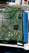
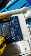
Can you provide some clear photos of your wiring so we can eyeball for any physical issues?
 
Here’s some wiring work sorry for the extremelylate reply
 

Attachments

  • IMG_8422.webp
    IMG_8422.webp
    989.4 KB · Views: 1
  • IMG_8421.webp
    IMG_8421.webp
    840.2 KB · Views: 1
I see some solder debris here you'll want to get rid of:

1786828432617.webp


You never know what sort of short this kind of solder/wire debris can cause, so please ensure you get rid of any that you find in your shell!
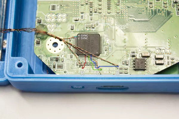
It looks like you have VGA enabled, but it doesn't seem like you have 3.3v soldered to mode like you're supposed to. IIRC you need to connect TP47 to 3.3v in order for the Wii to switch the video mode to VGA. The Gboy guide has a great reference image:

820a96c8-9a09-4f80-ac30-8c492af14ceb.webp


The green magnet wire above H-Sync and V-Sync is connecting TP47 to 3.3v. That's where the via runs to, and you can easily solder a longer wire for an easier solder joint.

It's also possible you've got the screen driver board on the wrong video mode. If you do, you'll need to plug in the screen control PCB and press the source button on it until you're on one of the VGA supporting modes. IIRC there's two of these modes, so annoyingly, you may need to toggle between these when testing until you find solve the problem. Hope this helps!
 
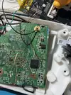
Thank you for the extremely detailed response! I never got a screen control pcb so i don’t know if that might be something you have to purchase separately? I cleaned up a lot of stuff and connected tp47 to a 3.3v source, but still no luck. I also think one of my problems might be the ground for the blue vga wire. I havent been super active on this project recently, but it looks like the ground via is really messed up (shown in picture). I can’t get a solid joint there. Is there a replacement nearby?
Edit:
I have resoldered all of the voltage wires and the vga wires (besides the ground for blue) i have also rewired u10, headphone sense, and scw. I made sure the board was clear and clean and i will be testing once i get my blue ground situation sorted out.
 

Attachments

  • image.webp
    image.webp
    1.1 MB · Views: 1
Last edited:
  • Like
Reactions: cy
I havent been super active on this project recently, but it looks like the ground via is really messed up (shown in picture). I can’t get a solid joint there. Is there a replacement nearby?
The ground via for the blue can go to any ground point realistically. Ground is abundant on these boards, and you can find it by using a multimeter in continuity mode (something you should know how to use if you don't already) and probing around various components until one is conencted to ground. Realistically, if you scrape away a bit of green solder mask on the motherboard in an area near the via that doesn't have any traces, you'll almost certainly expose some of the ground plane which you can solder to.

As for the screen control board... You're almost certainly going to need one of these or a substitute. You should be able to recreate the effect of the board yourself, but doing so requires knowing the correct resistor value for the "source" button. I'd measure it for you if mine was the same revision screen, but my driver board is older and may be different, so you may need someone else to do that for you.

I'm telling you all of this though because your problem is almost certainly the screen driver board being in the wrong video mode. Does it say VGA? or AV in the top corner of the screen when you power it on? If it says VGA, you should be able to get video out of it! If it's one of the AV inputs though, you'll need to change the mode for it with the screen control board or some alternative solution.
 
Back
Top