
Legend
.
Hey Guys,
So I picked up a 4-layer board this morning and installed Portablize Mii with no troubles, and ordered a RVL-PSU for now until I decide to get the PMS (actually I plan on doing the G-Boy before doing my own), so I decided to relocate bluetooth and U10 before trimming.
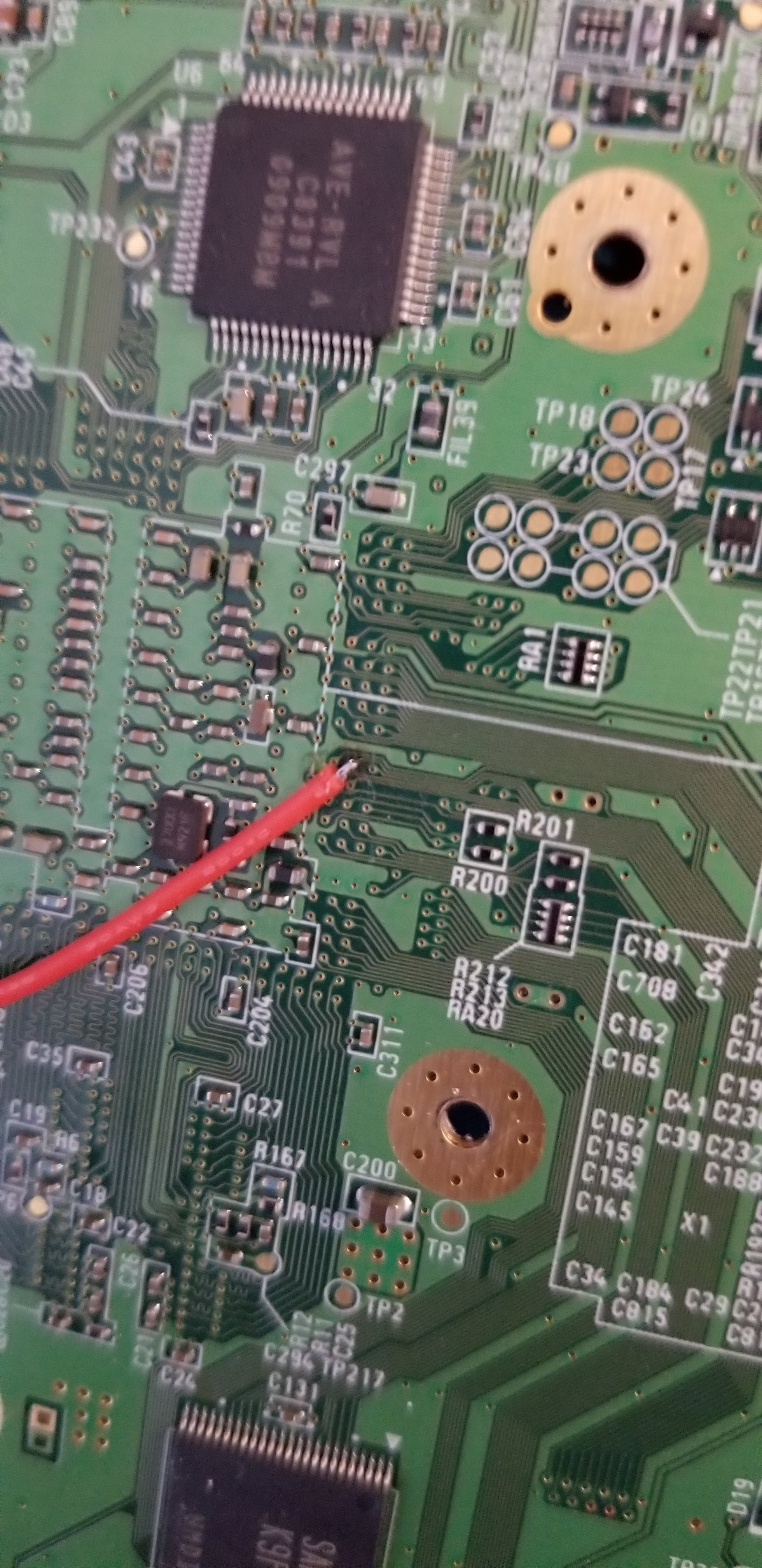
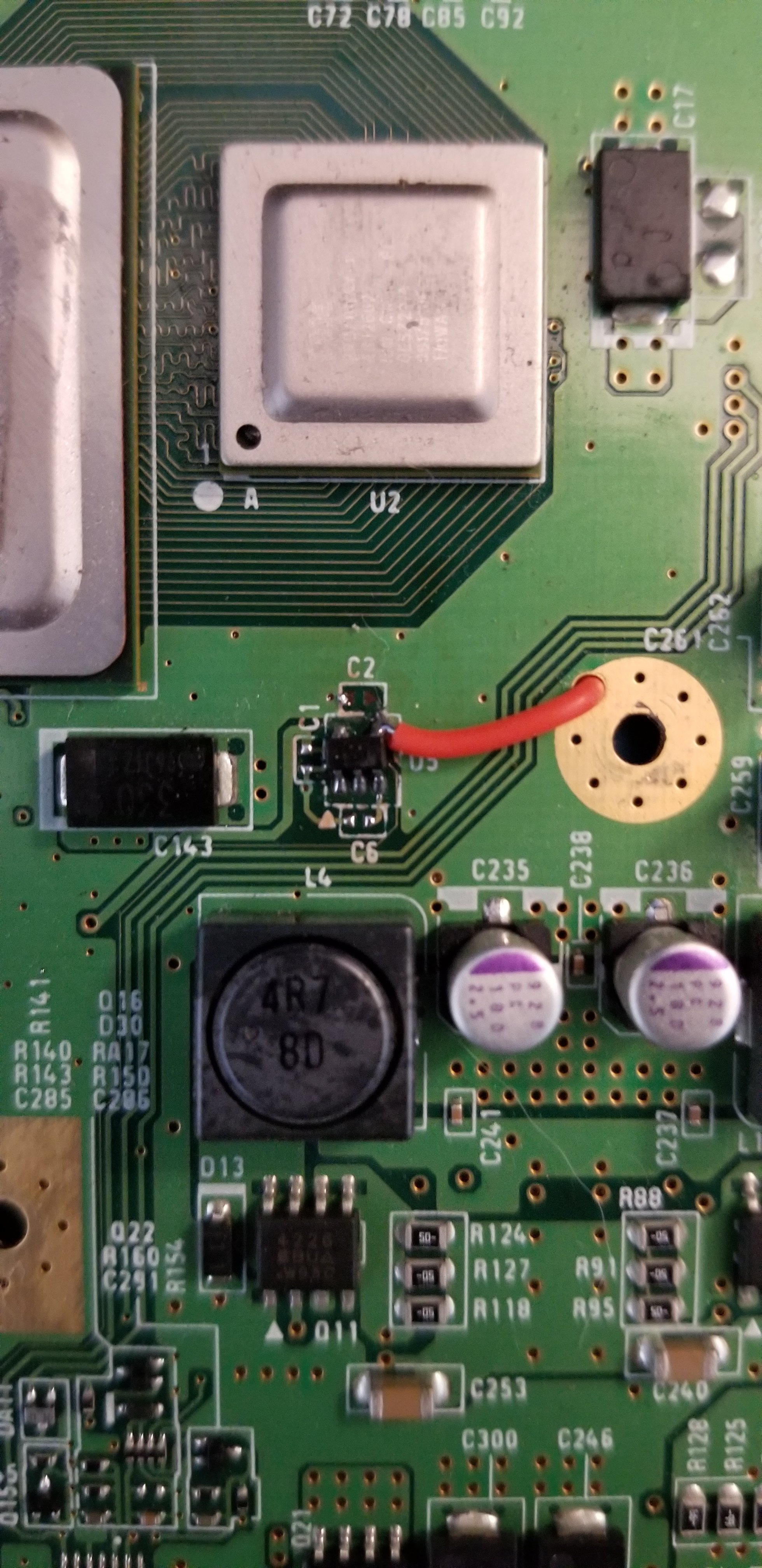
Bluetooth was fine, but U10 was giving me a bit of trouble. I had a hard time using hot air at 280* C to get the U10 off, so I used a combination of hot air and the "flooding" technique with my iron and it came off pretty good. I cut the trace, got it back on alright, and connected it to the GPU pin using 34awg magnet wire.
When I went to boot, it just gave me a red light, so the first thing I did was disconnect bluetooth and reconnect it normally, then reinspect my U10 wiring and nothing looked wrong. I also inspected the board for any solder blobs that may have flown off during the removal of the transistors, but found nothing.
So I removed U10 (with a lot less trouble lol) and checked the trace cut. I put U10 back on, then wired it to the GPU pin again, but temporarily using my 30awg striveday wire. The light comes up as almost an orange, but still no boot.
im pretty confident in my soldering and wiring so im thinking I just messed up U10 while removing and will have to use U9, but any ideas would be great. (Bigger wire does not look very good in picture but its solidly connected.)
So I picked up a 4-layer board this morning and installed Portablize Mii with no troubles, and ordered a RVL-PSU for now until I decide to get the PMS (actually I plan on doing the G-Boy before doing my own), so I decided to relocate bluetooth and U10 before trimming.
Bluetooth was fine, but U10 was giving me a bit of trouble. I had a hard time using hot air at 280* C to get the U10 off, so I used a combination of hot air and the "flooding" technique with my iron and it came off pretty good. I cut the trace, got it back on alright, and connected it to the GPU pin using 34awg magnet wire.
When I went to boot, it just gave me a red light, so the first thing I did was disconnect bluetooth and reconnect it normally, then reinspect my U10 wiring and nothing looked wrong. I also inspected the board for any solder blobs that may have flown off during the removal of the transistors, but found nothing.
So I removed U10 (with a lot less trouble lol) and checked the trace cut. I put U10 back on, then wired it to the GPU pin again, but temporarily using my 30awg striveday wire. The light comes up as almost an orange, but still no boot.
im pretty confident in my soldering and wiring so im thinking I just messed up U10 while removing and will have to use U9, but any ideas would be great. (Bigger wire does not look very good in picture but its solidly connected.)
Attachments
-
 1.1 MB Views: 235
 -
 1.1 MB Views: 192