Worklog The Wii SPii

StonedEdge

a.k.a. ClonedEdge
.
.
Joined
Nov 16, 2018
Messages
362
Likes
1,482
Location
Japan, Tokyo
Portables
2
Test prints are in! I was able to shave off 5mm from the old design. It is now 41.5mm thick from top to base in comparison with the red model, which was 46.5mm.

The new shoulder buttons truly feel really awesome compared to the old ones!

Not much CAD work left to do now. After I’ve ironed out a few flaws, it’ll be time to order the PCB and do this all over again...

7B5F90DF-5323-4D8E-AF7E-6BD061C6A11E.jpeg
2DE5D073-047D-4677-BB50-8C5A4B889A91.jpeg
220DF22F-504D-46CD-A8EB-CF7E588B1E91.jpeg
 

StonedEdge

a.k.a. ClonedEdge
.
.
Joined
Nov 16, 2018
Messages
362
Likes
1,482
Location
Japan, Tokyo
Portables
2
I've been working very hard on making a lot of changes to the PCB (again it feels like it never ends... I make a small mistake and then everything needs to be fixed again kek). I've now incorporated the Bluetooth module and MX chip onboard, as well as a CR1025 cell to power the MX chip for RTC functionality. There is literally no space to mount any of these daughterboards on the Wii like in most portables, so I took it into my own hands.

I thought some people may be interested in knowing the differences between the two builds, so I think it's a good time to list any of the differences that exist between this revision and my contest entry. Definitely some major improvements going on!
  • MicroSD card to USB converter onboard (GL827L IC) - now no need for the kingston microUSB adapter
  • Brand new trigger mechanism (hall sensors for analog, PCB mounted digital buttons actuated by some music wire)
  • Entirely machined triggers made from Delrin (no springs necessary, self returning)
  • Completely new dpad design
  • Larger action buttons for comfortability (Do I have the right to say this lol - this thing is disturbingly uncomfortable)
  • No battery clips (not enough room, very hard to fit in the small case, so I will be directly soldering to the cells - please spare my soul Aurelio)
  • Screw posts for absolutely everything including the Wii - Wii standoffs slide through the all in one PCB and secure the Wii into the front of the case instead of the back housing like most portables do
  • Replaced cheap ass, crappy digikey volume pot with larger, smoother RK10J1_R pot for better feel
  • No GC+ wires, all buttons on the PCB (one wire only to the Wii for data)
  • Switch stick FFC connectors now perfectly aligned on top of PCB (no breaking/twisting of any FFC connectors now like I had to before!)
  • Tiny TPS regulator modules for 1v, 1.15v, 1.8v and 3.3v step down voltages (all have inbuilt inductors)
  • Entire case is designed with machining in mind! The case can be machined in a variety of different materials down the line (such as out of a billet aluminum block/acrylic or 3D printed for extensive testing/test fits/prints thanks to radiuses on all internal corners) - thanks Dmcke5 <3
  • Reduction in thickness of 4mm in from the previous model (lid to batteries)
  • Much better placement of the BQ25895 IC. I moved the microcontroller to it's own part of the board which freed up a lot more space for routing. Hopefully it will stay cool this time when charging and playing. I plan on popping a small little heatsink on top of it to dissipate some of the heat generated.
  • 45 degree ICs, what is this sorcery
This will probably be the last update on BitBuilt before finalizing everything up and then ordering the PCBs from JLCPCB. Hopefully I'll have a test print done soon from my Prusa and be able to show that everything fits. After that, Dmcke5 and I will get to work on machining the case on his CNC with a 30mm acrylic block of plastic. Can't wait to see how it is turning out, I hope you're excited as I am :D:D

Back_closed.PNG
SPii Stackup.PNG
Inside Back.PNG
Front_BT_MX.PNG
Front.PNG
 
Last edited:

StonedEdge

a.k.a. ClonedEdge
.
.
Joined
Nov 16, 2018
Messages
362
Likes
1,482
Location
Japan, Tokyo
Portables
2
I got bored this week since work was quite quiet and thus added all of the components onto the PCB. Some of the non-standard models were hard to find so I didn't include those. Maybe I will make them to put on the board later on though when I get some more time.

Back view with all the components placed on the PCB:

1602741292915.png


Hall sensor/analog trigger progress (birds eye view):

Currently this is still a big WIP. The magnet is a little too close/large to the sensor face for the hall sensor I've chosen to use - at least based on the calculations from the calculator (which has a sensitivity value of 5mV/G). Dmcke5 and I are going to be performing some more practical tests in the coming weeks to see what readings we will get when the trigger is released/fully actuated. Obviously the calculator is not 100% perfect. The sensor we've chosen only measures/reacts to a directional magnetic field, so we need to take that into account with our measurements as well (not total magnitude). Big thanks to Bob (robertlong13) for helping explain how this works (I'm a little bit inexperienced when it comes to electromagnetism and how it all works, but currently learning!). Right now, I've got an N52 grade 4mm diameter x 2mm thick round magnet in there to generate the magnetic field, and am using this calculator to do basic calculations based on the X/Y distance of the magnet from the hall element https://www.kjmagnetics.com/fieldcalculator.asp.

I'm aiming to make the sensor output voltage vary between 1.5 and 4V, with 2.5V as the middle value, since that is the quiescent voltage output of the sensor (before the divider). We can then hopefully handle the rest in software with GC+2.0 to scale the voltage values to range between 0 and 3.3V on the output - I don't think it will be as difficult as I am thinking it will be, but we'll see how it goes! Main concern is going to be getting any sort of linearity out of analog triggers in such a small handheld. It’ll be more “on and off” rather than any sort of precise control most probably.

1602741331489.png


1602741847130.png
 
Last edited:

StonedEdge

a.k.a. ClonedEdge
.
.
Joined
Nov 16, 2018
Messages
362
Likes
1,482
Location
Japan, Tokyo
Portables
2
Began the toolpathing with Dmcke5 tonight in Fusion 360! It's my first time seeing toolpathing done. It is definitely a lot more complex than just using 3D slicing software. Tomorrow night if all goes well, we may be streaming the CNC machining aspect/more toolpathing, but we will see how it goes. Will be sure to post a live stream link in the Discord when we go live! Not sure if this will be the final build or not, but the case will be acrylic - maybe translucent painted in blue? (I haven't fully decided yet on the post processing side of things, but how can you not be excited at least for a CNC'd case? :D :XD:)

1603286638611.png
 

StonedEdge

a.k.a. ClonedEdge
.
.
Joined
Nov 16, 2018
Messages
362
Likes
1,482
Location
Japan, Tokyo
Portables
2
Dmcke5 and I machined the top half of the SPii yesterday and then Dan was kind enough to sandblast it for me! Looks like it was carved out of an ice block, I’m really, really digging it.

75E5D931-62A4-4B9C-9B47-8EC86A07E7CA.jpeg

2BE6C8DF-F29F-4F03-A0FE-61127F3E2837.jpeg
214BCF91-94E2-4BB7-8879-983BD4AD0800.jpeg
 

StonedEdge

a.k.a. ClonedEdge
.
.
Joined
Nov 16, 2018
Messages
362
Likes
1,482
Location
Japan, Tokyo
Portables
2
The new "Wii SPii rev 1.3 PCBs" arrived from JLCPCB yesterday. The parts from Digikey will be here tomorrow, which means assembly will probably happen this weekend if I am not lazy. I plan on assembling everything in a 3D printed prototype case, and then moving all the components to the CNC'd case from Dmcke5 when that arrives hopefully in a month or so. Fingers crossed I haven't made any stupid mistakes!

Ayy 4.jpg
1604471950166.jpeg
Ayy 2.jpg
Ayy 3.jpg
Ayy.jpg
 

StonedEdge

a.k.a. ClonedEdge
.
.
Joined
Nov 16, 2018
Messages
362
Likes
1,482
Location
Japan, Tokyo
Portables
2
I accidentally ruined my PCBs with a VSYS to GND short... I won't get into it but I'm onto Revision 1.4 (welp). It was a simple mistake and I got to use Gman's JLCPCB discount code anyway. There always a silver lining. Oopsies.

Due to popular demand, I've made a 3DS slider version that is 2.5mm less thicc. I just need to modify the PCBs for this to fit, but I will be open sourcing both versions for anyone who wants to have a crack at building one! Thanks to Gman for sharing the awesome models for the slider. These made it a breeze to integrate into the design. I also started fiddling around with some ball pivots for the DPAD to make it slightly less bad? We will have to see how it turns out. As you can see, a pretty big layout change is going to be required for this to happen so it might be a while before I release both versions. Sliders are actually way bigger than switch sticks.

Comparison.PNG
Ayy.PNG

225F9D35-5A36-454A-BFFA-DCD7CC9C7733.png
 
Last edited:

StonedEdge

a.k.a. ClonedEdge
.
.
Joined
Nov 16, 2018
Messages
362
Likes
1,482
Location
Japan, Tokyo
Portables
2
SoonTM
:D

98DC404D-DDA4-45A1-9B77-536387C7CA2A.jpeg
1F06E0C4-28DB-464C-982B-BED416D60765.jpeg
98DC404D-DDA4-45A1-9B77-536387C7CA2A.jpeg
1F06E0C4-28DB-464C-982B-BED416D60765.jpeg
Ayy2.jpg
Ayy1.jpg
Ayy 4.jpg
aYY 5.png

D466B0CB-D022-400C-B8E5-7592DC25A45E.jpeg
 
Last edited:

StonedEdge

a.k.a. ClonedEdge
.
.
Joined
Nov 16, 2018
Messages
362
Likes
1,482
Location
Japan, Tokyo
Portables
2
I made another PCB that accommodates 3DS sliders instead of switch analog sticks. This required that I pretty much re-design 60% of the mobo from scratch, but I much prefer this layout. Now people can choose whatever they want when they build one (and also stop complaining that I didn't use them in the first place!) :XD:

The start button doubles as the sync button for Bluetooth, since the sliders don't have any R3 button built in. The headphone jack is slightly off center but I don't think anyone will notice. Everything was much easier to route compared to the switch stick version this time around. I also added some squishy/clicky buttons that Gman used in his N64SP compared to the thin dome tacts I used in the non-slider one. Interested to see how those will feel in comparison! Looking forward to building the slider verison! I may or may not be stealing Gman's funtastic case idea for that one too.

AYZ.PNG

Slider PCB.PNG
 

StonedEdge

a.k.a. ClonedEdge
.
.
Joined
Nov 16, 2018
Messages
362
Likes
1,482
Location
Japan, Tokyo
Portables
2
The SPii case arrived in one piece and the quality feels really fantastic. No, like, amazing. It's hard to describe but its very silky soft thanks to the sandblasting, maybe very close to an injection molded piece for a much cheaper price. I put all the parts inside to make sure they all fit like a glove, and they do! It is definitely rewarding after months of hard work with Dmcke5 to see it pay off. A huge thanks to him for all of his excellent work.

I have a bit of spare time this weekend so I will begin the assembly process. Aim is to have it completed by the date of "soonTM!" Hopefully it goes well.

DFB2369F-3EED-4279-AF8E-48BFBF7C2A21.jpeg

127918346_191857535896189_3509048537952819172_n.jpg
128686192_1062864650829380_643395968504917016_n.jpg
128081475_1312561672425989_4953021394618304_n.jpg
126203665_228340028647436_6181840243064966204_n.jpg
127649401_397202944669621_7363719081456064630_n.jpg
 
Last edited:

StonedEdge

a.k.a. ClonedEdge
.
.
Joined
Nov 16, 2018
Messages
362
Likes
1,482
Location
Japan, Tokyo
Portables
2
Not a major update, but I've started testing a couple of things with the new PCB. The screen has been giving me a bit of a headache at the moment. I bought a new 3.5" panel as my other one had stopped working, and I'm currently getting a very unstable backlight that switches on and off sometimes on startup (other times it works completely fine with no issues). The driver board is very old and quite battered (like, 6 months old) so I've ordered a new one to hopefully fix my issues. One interesting thing I noticed after discussing with Yveltal is that the newer 3.5" VGA 640 x 480 panels have a slightly different layout on the ribbon cable, with the older panel having an extra microcontroller presumably handling the startup sequence. We thought maybe that the newer panels have the initialization code embedded within the RTD driver onboard the panel, but not entirely sure about that - probably unrelated.

131430997_390218938719766_6707693639827460257_n.jpg


I'm currently powering the screen rails separately on 5v, 3.3v and 1.8v with 30AWG wire. There doesn't appear to be any significant voltage drop or heat generated in the wires so I am quite sure this will be fine (I need the wires to be thin to run them through the small hinge slot). I tried with thicker wires but this doesn't seem to change the backlight problem below. Currently I have a 22uH inductor on there as I lost the original inductor which was 10uH. I need to find a suitable replacement for it because of height restrictions of the case lid. Direct Drive would be perfect, but it's not available yet for the 3.5" panels, so I will have to find a suitable replacement. I plan on probably just getting a 10uH ferrite inductor again that closely matches the specs of a wirewound CD32 standard inductor, but not sure. I should have some wiggle room given that the backlight converter is a switching regulator. As long as I can find something with a similar saturation current and DCR value I should be OK here. Something like this seems like it will work fine. The boost converter is the PT4103 which seems like most Chinese fabs are using this one for driving the LEDs in series.


Anyway, its working sporadically at the moment (75% of the time it will boot up, other times the screen will just flash on and off on startup - see video below).


I am sure I'll be able to iron these out soon! I also screwed up the PPS input signal reset value in code accidentally, as the wiper pin was incorrectly mapped to the wrong pin of the microcontroller. No wonder I wasn't getting any audio output. I've reconfigured that and will try again hopefully to get some audio this weekend. Last step once I've got everything working in a somewhat stable manner will be quickly adjusting the LA/RA values in GC+2.0 for the analog triggers. These aren't going to be the best I don't think given the range limit of the hall sensors but should be good enough for a first build.

131958119_192868762515107_5456485037475434603_n.jpg
 
Last edited:

StonedEdge

a.k.a. ClonedEdge
.
.
Joined
Nov 16, 2018
Messages
362
Likes
1,482
Location
Japan, Tokyo
Portables
2
Very close to finishing this off, probably within the next couple of weeks. My Chinese switch sticks were broken so I’m still waiting on a spare in the mail, but everything is confirmed pretty much working at this point, which makes me very happy!

I made a critical error with my hall sensor circuitry and the voltage divider, basically tying the resistors (top of the divider) to a 5V input instead of the analog output of the hall sensor... woops. Always pays to double check everything... Thanks to robertlong for helping me debug that today. A couple of cut traces with an xacto and bodge magnet wire does the job. (Plus a trimmed hall sensor output leg, lol)

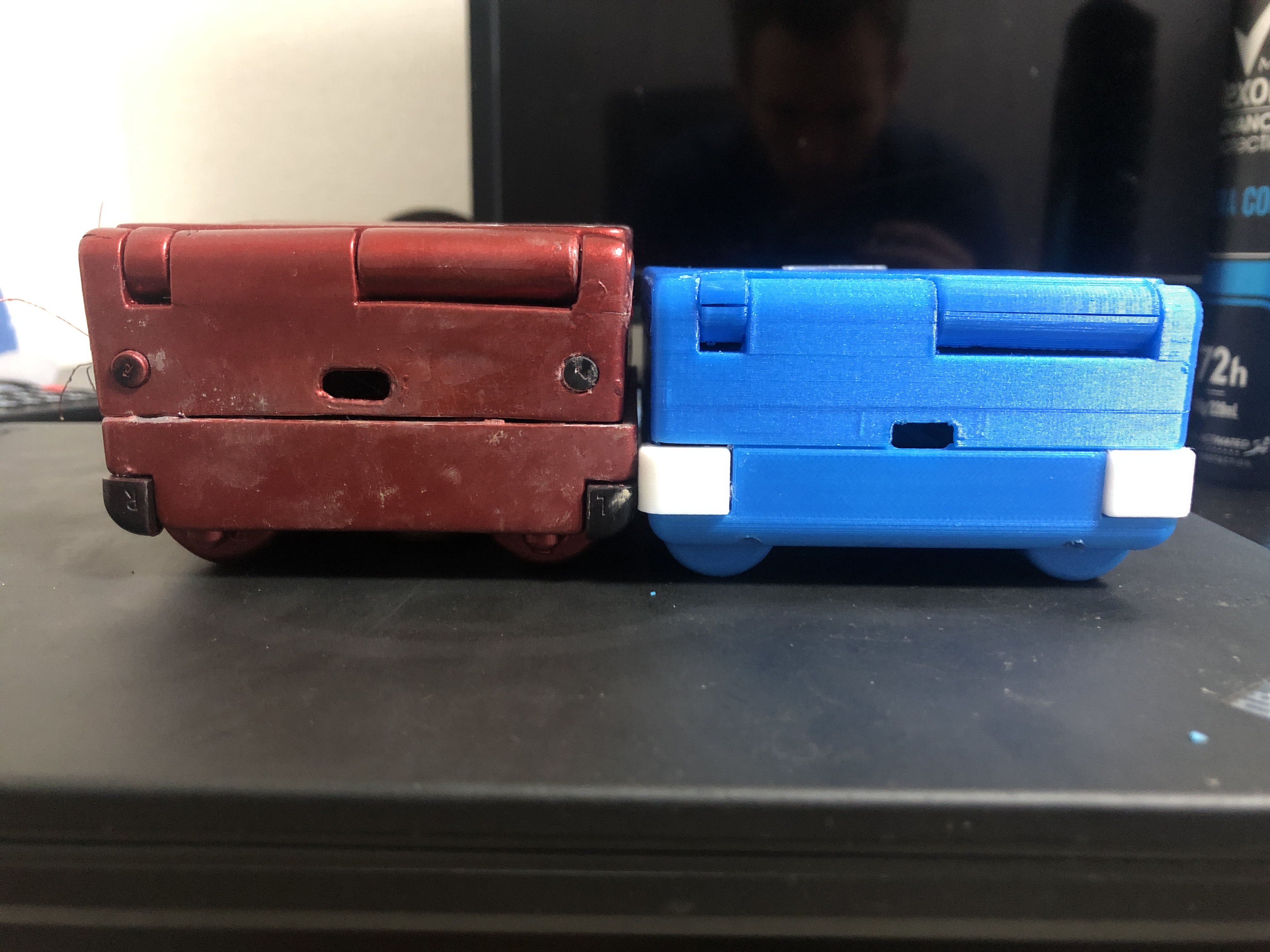
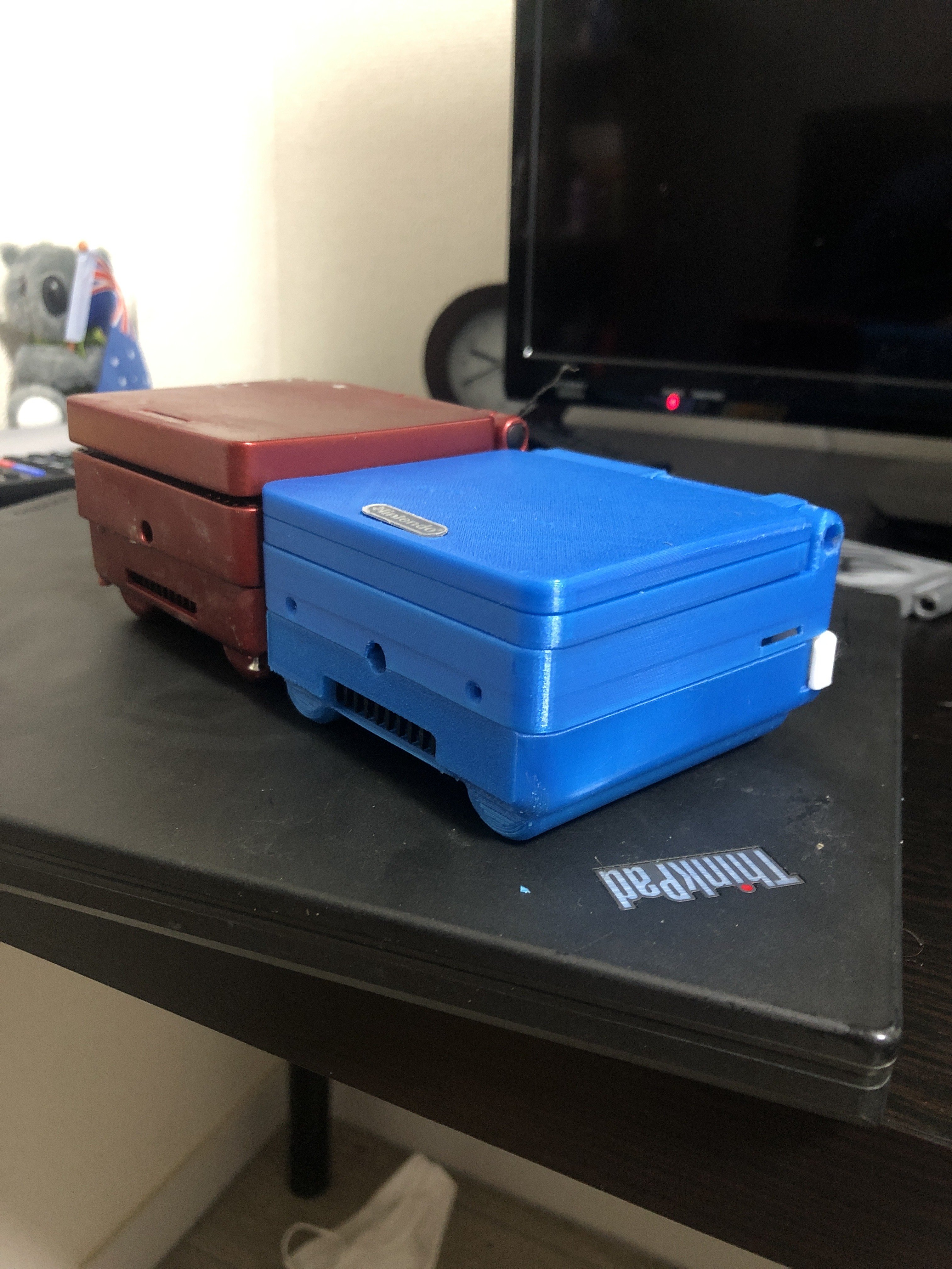
I also had to put aside my LMAO trim as it was just not consistently booting. I think some thermal adhesive got underneath the chips and probably flexed the GPU as it hardened. I was constantly getting 2.8v on the output of the u10 and after replacing it with several others, the issue persisted. I may try reflowing the GPU and salvaging it at a later date. I’ve thrown in an OMEGA trim I had lying around from YveltalGrififn. This has the AVE-relocation performed and also a NAND relocation. The soldering is really well done. It makes my case look huge!! He’s done an excellent job, wouldn’t expect anything less from him! It’s mounted in a similar fashion to how Gman mounts his PS2 and N64 portables, with two little 3D printed tabs. The case is designed for a LMAO trim, but until I receive the NAND flex boards from the store, I can’t really proceed so I thought why not make use of the OMEGA!

Dmcke5 and I worked on the analog trigger code together and set up LUTs for GC+ 2.0, as well as easy scaling parameters that take the min and max ADC values and scale them to a 0-255 range. Both ended up having around 70 points of precision, which isn’t much, but for 2-3mm traveling triggers, who is going to notice? Thanks to Pizza Lord as always for optimizing everything and immediately fixing code issues in like 5 seconds lol

I’ve been having some issues with the code, but considering it’s running GC+ 2.1 firmware currently (which had issues with analog triggers) instead of the latest firmware, that is apparently expected and hopefully will be fixed once I update the code and flash the newer firmware.

Its all coming along very well, though :D:D

82A1F07C-1BDA-4E3B-897C-5D0A1052C135.jpeg
B6EE0FCE-67D0-46B7-8884-962A00139569.jpeg
39000DC2-AA2D-438A-973E-C7A975F85813.jpeg


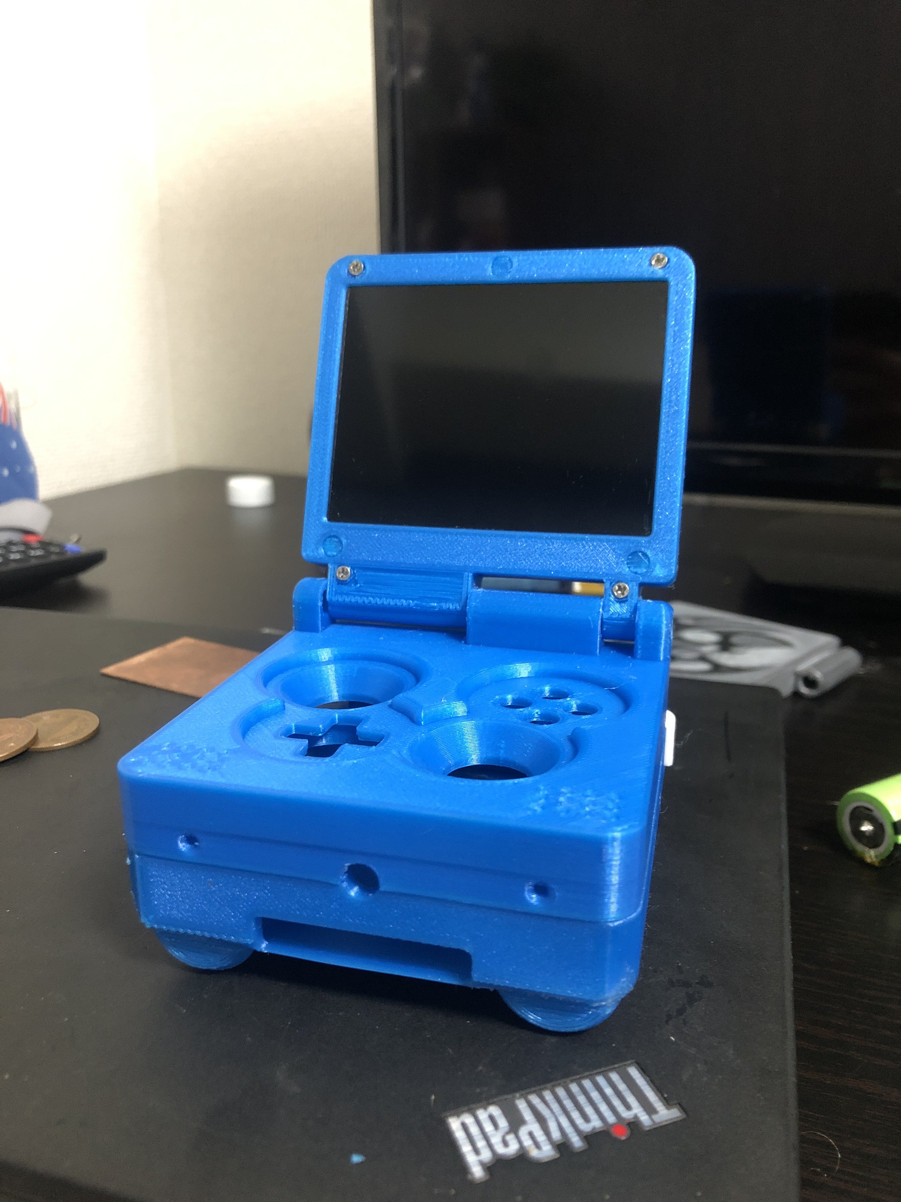
Analog triggers. They definitely were a hurdle to design around but given space constraints, definitely a great solution I think and still give some control compared to dual tacts :XD:

 
Last edited:
Top