Solved Relocating cart slot problem

GC64

.
Joined
Jul 3, 2016
Messages
177
Likes
153
Location
Georgia
Portables
2
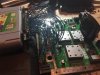
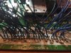
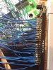
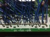
Well this was my second attempt at relocating the cartridge slot, and both seemed to fail despite my ultra precison on the second attempt. I'm using 28 awg wire. This time when I boot up the game, the red light flashes and I hear a ticking noise. This can be prevented by pulling on the cart/wires upward. Any suggestions on why it might not be working? I tried on two different n64's and two different cart slots. The first cart slot's pins were bent back to make it easier to tin them, so I didn't bend them on the second try because I thought I might've broken a joint. Also, do the length of the wires all have to be the same? They're all close to the 5 inch mark but some slightly vary because of stripping.
 

Attachments

Noah

retired
.
.
Joined
Jan 16, 2016
Messages
1,968
Likes
2,567
Location
The World Wide Web
Portables
Can you get a closer image of the wiring on the board? If they are short enough my guess is that you've got a short somewhere. From the image you posted it looks like there are large blobs of solder which may be touching one another.
 

GC64

.
Joined
Jul 3, 2016
Messages
177
Likes
153
Location
Georgia
Portables
2
Can you get a closer image of the wiring on the board? If they are short enough my guess is that you've got a short somewhere. From the image you posted it looks like there are large blobs of solder which may be touching one another.
Well I ran a flat head between each joint to make sure none were touching each other and I dont believe any were. Also, not only am I bad at soldering but I also added tons of it because the wires kept slipping or breaking off. I reused the same wires for the second relocation so they're getting weak (could be the problem?)
 

Attachments

GC64

.
Joined
Jul 3, 2016
Messages
177
Likes
153
Location
Georgia
Portables
2
It looks like you may have shorted some of the cartdrige port wires with the expansion port holes
You mean the small holes in the middle where the pins originally went through? I had no idea they weren't allowed to be touched since the pins were originally in their place. Well either way, I fixed the wires touching those holes and it still didn't work :/
 

Noah

retired
.
.
Joined
Jan 16, 2016
Messages
1,968
Likes
2,567
Location
The World Wide Web
Portables
One last thing you could try is to check continuity with a multimeter if you've got one. If they are all connected to the correct pad then I'd redo the relocation with shorter wire.
 

ShockSlayer

the real
.
.
Joined
Jan 16, 2016
Messages
1,512
Likes
3,940
Location
standing up
Portables
please do not ask!!!! I will NOT respond
The holes in the middle aren't connected to anything, the main slot is connected to the expansion slot pins through that.

However, the outer 12 pins are all connnected to GND, which could cause issues if they're maybe bridged like this:


Anyways, your wiring is kind of a mess. Redo the whole thing, twist the wires before you put solder on them, then cut them shorter and then solder them on top of the expansion pins. There are a lot of little GND vias around some of those pins that can also potentially short them out.
 

Pacal

.
Joined
Jul 30, 2016
Messages
159
Likes
341
Location
Seattle W.A
Portables
RDP 64
What about the cart slot,are any of those wires touching each other?because in the picture they kinda look like they touching
 

GC64

.
Joined
Jul 3, 2016
Messages
177
Likes
153
Location
Georgia
Portables
2
The cart slot joints are all separated, none touching each other. And about redoing the whole thing, I've already been on top of that. I cut 48 new wires and will flatten them straight overnight, rather than letting them curl. This way it will be far more neat and not tangled. One of the main problems with the first two attempts was the little strands from the wires were scattered everywhere and caused shorts I'm sure, so I'm just redoing it a third time. Also, the pictures were shot at some bad angles, so in a lot of places it looks like they were soldered to other pins. I've checked each pin at least 15 times now, so my conclusion was that one of the wires is broken somewhere. Oh well, I will hopefully have the third attempt done tomorrow.
 

GC64

.
Joined
Jul 3, 2016
Messages
177
Likes
153
Location
Georgia
Portables
2
Last edited:

Pacal

.
Joined
Jul 30, 2016
Messages
159
Likes
341
Location
Seattle W.A
Portables
RDP 64
you need the pin 45 if you want to play all the games but the pin 45 its also for the everdrive so if you have one and want to use it you need that pin
But also you need to connect 5 wires more for the everdrive but only for the everdrive And for the wires just cut them 5 inches long
 

ShockSlayer

the real
.
.
Joined
Jan 16, 2016
Messages
1,512
Likes
3,940
Location
standing up
Portables
please do not ask!!!! I will NOT respond
Connect them all. I have a quote about this I saved from @marshallh a couple years ago. The first time I'd ever used a 64Drive was at MRTN. Both @Ashen and @ttsgeb had one, and while they worked fine on Ashen's N64p, they didn't work on the one I had RCP wired, even though all my other games worked fine. So we PM'd marshall and he told us this:

"Make sure you have enough ground/3.3 wires. They are really all required. The 64drive draws a bit more current than a standalone cart and may not work with insufficient power."

The same could be said of any cartridge. If you've ever opened up a couple 64 carts, there are a lot of different types, some only have two chips, some have 3, some have 4, etc... In addition, multiple grounds will help tremendously with the bountiful interference found in portables.

So basically if you want things to work best, then you should really use them all. Also, I don't know where this not connecting pin 45 nonsense comes from; it's connected to both the PIF and the CPU, so I'd say it's probably pretty important.
 

GC64

.
Joined
Jul 3, 2016
Messages
177
Likes
153
Location
Georgia
Portables
2
Ok this doesn't make sense. I cut brand new wires, all 5.75 inches long, I fluxed every single one so they are going no where, and it is neat af. I can almost guarantee you there are no shorts. Wtf is the problem? Is the board fried? The light turns on so.. check attached images for the wiring.
 

Attachments

GC64

.
Joined
Jul 3, 2016
Messages
177
Likes
153
Location
Georgia
Portables
2
5.75 still may be too long. If you've got the 64DD slot still connected on the bottom put the cart slot in and see if it reads the game.
64DD slot is not attached anymore and the pins were broken off. I don't understand why 5.75 is too long, what is a good length? I mean I've seen people do it over 6 inches..
 

Noah

retired
.
.
Joined
Jan 16, 2016
Messages
1,968
Likes
2,567
Location
The World Wide Web
Portables
The farther away you get the more unstable things will get. I keep it as short as possible for the case I'm using. Normally 4-5 is the sweet spot I use.
 
Joined
Jul 25, 2016
Messages
163
Likes
121
Location
US - Tallahassee, Fl
Portables
3/4
That's what I've heard both from reading on the cart relocation and in different videos I've watched was to try and keep the relocation wires as short as possible to prevent it from becoming unstable or not working. I think I read somewhere that 3 to 4 inches was the suggested length, but it might depend on the actual motherboard too. Even though they are mass manufactured they all tend to have different tolerances when t comes to what they will and won't do.

I have two identical screens I ordered off eBay for my projects, same driver board and model screen but one runs great as far down to 8 volts, (didn't really test any lower) but the other doesn't like anything under 9 or 10 volts before it starts getting bars of static and interference. It's possible you got a finicky board?
 

GC64

.
Joined
Jul 3, 2016
Messages
177
Likes
153
Location
Georgia
Portables
2
That's what I've heard both from reading on the cart relocation and in different videos I've watched was to try and keep the relocation wires as short as possible to prevent it from becoming unstable or not working. I think I read somewhere that 3 to 4 inches was the suggested length, but it might depend on the actual motherboard too. Even though they are mass manufactured they all tend to have different tolerances when t comes to what they will and won't do.

I have two identical screens I ordered off eBay for my projects, same driver board and model screen but one runs great as far down to 8 volts, (didn't really test any lower) but the other doesn't like anything under 9 or 10 volts before it starts getting bars of static and interference. It's possible you got a finicky board?
I dont see how it being finicky would relate to it not being to relocate entirely. Are you saying that the board might not be able to handle 5.75 inches? If so then I'll cut them as short as possible.
 
Joined
Jul 25, 2016
Messages
163
Likes
121
Location
US - Tallahassee, Fl
Portables
3/4
This is true but I'm not sure, just throwing out any ideas I can think of that might/could help. I just know that I have run across some electronics that tend to be picky when it comes to wire lengths and voltages.

Here is a video from a YouTube video series from a seasoned veteran that I've been watching, (this is one of many from "MODDEDbyBACTERIA" that have shown me a lot. Here is where I got the 3 inches from but I've heard it in other videos too. Hope it helps!! :)
 
Top