Worklog NucDeck

Dmcke5

.
2020 1st Place Winner
Joined
Feb 16, 2020
Messages
216
Likes
885
Location
Queensland, Australia
Portables
3
Hi guys, I'm back once again to taint your forum with one of my "not a console" handheld gaming devices!

I'm doing a bit of a Youtube series about this project but I decided that I should probably have a forum post somewhere too to help record the finer details of the project that don't make it into the videos.
After I finished my DIY UFO back in 2020 I decided that I really needed a bit more power so I've been thinking about this project ever since. I've been pretty busy with renovations, work and family stuff so its taken a couple of years and now that handheld windows machines are readily available this project makes a lot less sense but I still wanted to give it a go.

My aim is to cram a mostly un-modified NUC into a housing that loosely resembles a professional product. I'm trying to keep the design relatively simple as I'm going to open source this project once it is complete. The housing is also a bit thicker in most places than my past CNC'd designs to try and make it possible to print.

Here's a tentative list of features I'm aiming for:
Any generation of NUC (I've chosen a 7th gen i5)
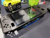
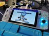
7" 1024x600 display
Touchscreen
4s 3000mah Lithium Battery (45 watt hour)
Battery/controller infomation display
USB-C charging
Gyro aiming
RGB joystick surrounds
Full sized joysticks
Analog Triggers
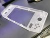
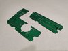
CNC machined acrylic housing

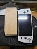
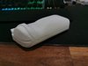
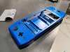
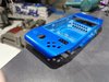
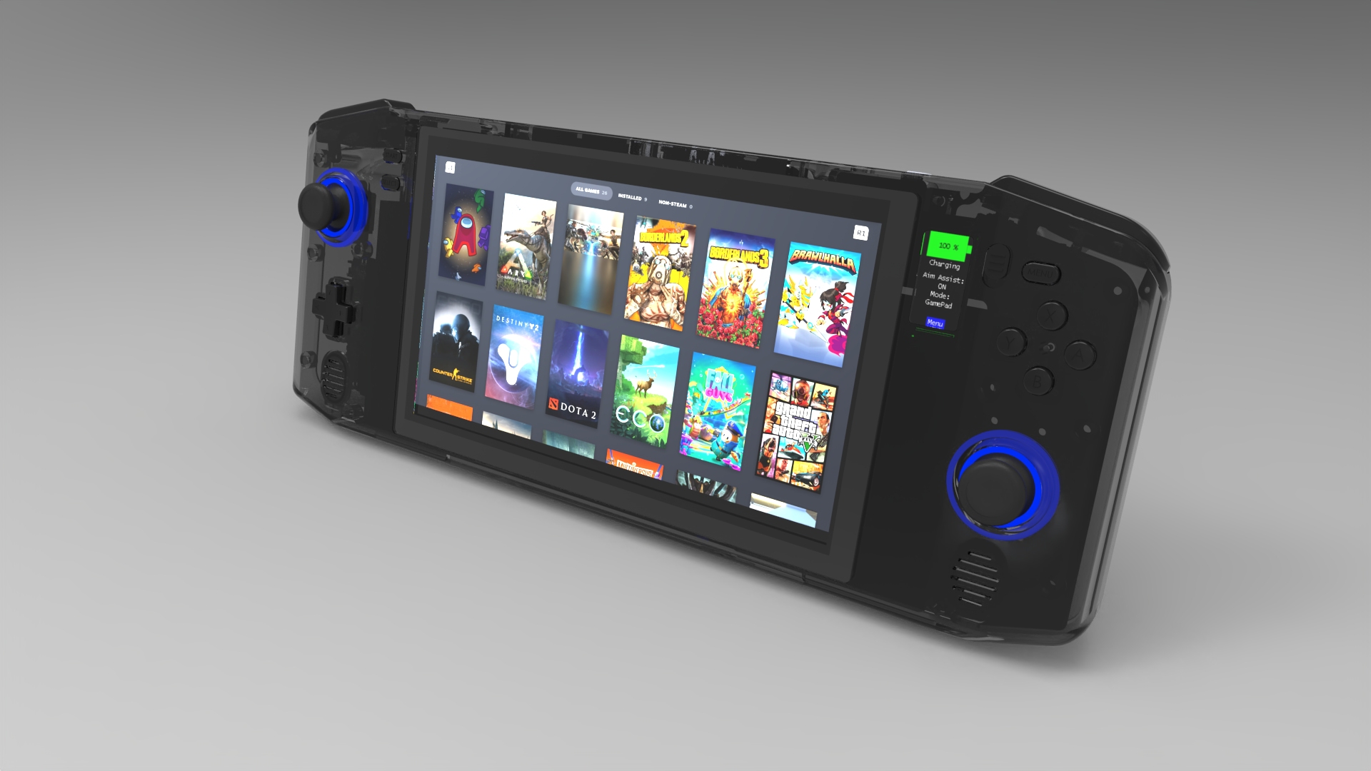
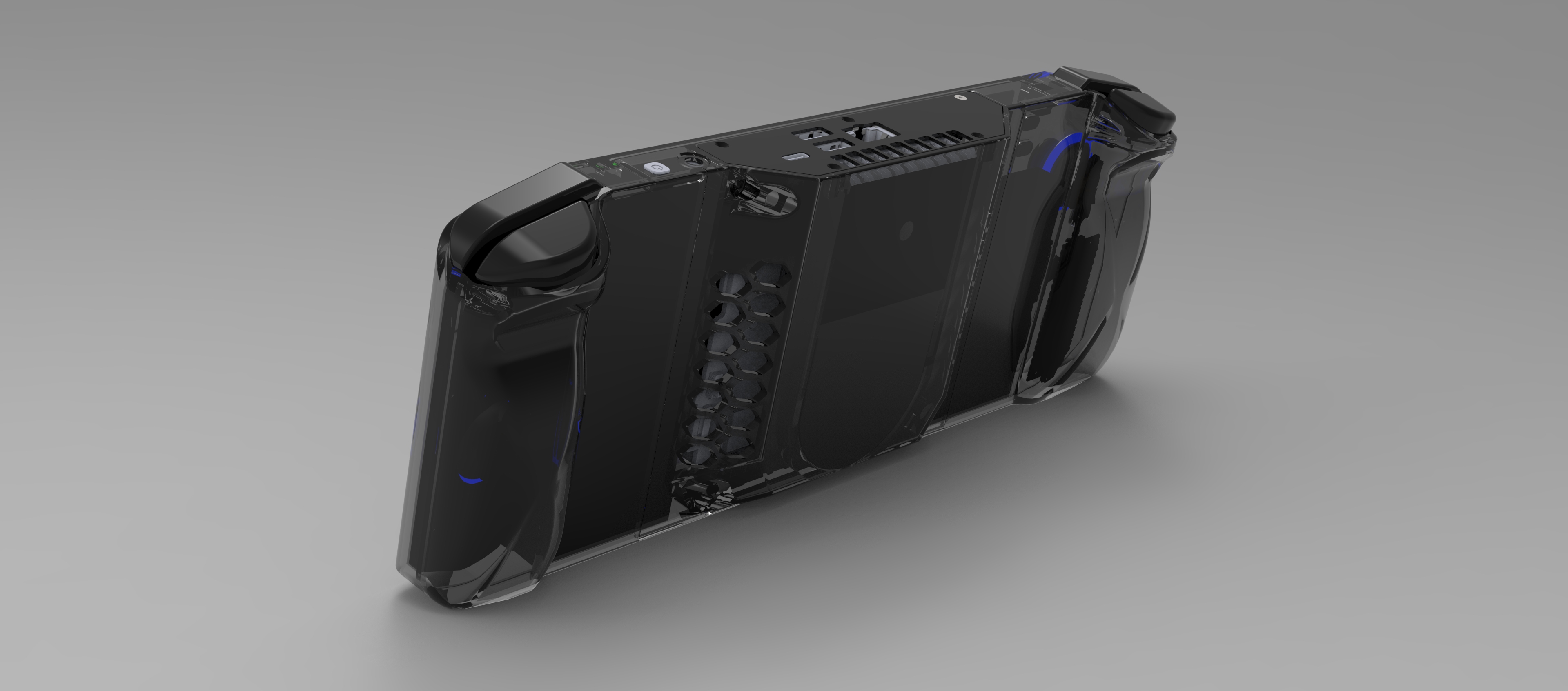
Here's a couple of quick renders I did of it once I had the design pretty much locked down.


NUCDeck.jpg
NUCDeck Back.3.jpg


I'm going to slowly fill out this worklog to catch up to where I am with the project so far but in the mean-time here's some links to the first three Youtube episodes:
Episode 1
Episode 2
Episode 3
Episode 4
 
Last edited:

Dmcke5

.
2020 1st Place Winner
Joined
Feb 16, 2020
Messages
216
Likes
885
Location
Queensland, Australia
Portables
3
The first step I made was in roughly February 2022. Once I had the initial shape and size worked out I ripped a very quick test piece out of a scrap of MDF I had to test the size and feel. I've also included a side by side photo with the DIY UFO for a size comparison. I eventually marked the front surface of this with some comfortable positions for joysticks and buttons. This is where life got in the way and I got distracted with renovations!

IMG_20220202_175913.jpgIMG_20220202_180016.jpg

Fast forward to March 2023 and I started printing some prototypes to get the shape of the grip and the position of the trigger and shoulder buttons comfortable. This is around the time I decided it would be a good idea to make this into a Youtube series so I started buying supplies.
IMG_20230303_193535.jpg

I settled on ALPS rkjx21224001 joysticks which I think are used in some of the GPD handhelds. I like these joysticks are they are very compact whilst still offering a "full sized" joystick feel. They are also compatible with Xbox one joystick caps which are readily available in many different colours.
IMG_20230324_152041.jpg

I picked up some 7" capacitive touch panels from Aliexpress. They are from a kids tablet so there is no front facing camera hole to worry about. They don't have a touch controller built in though so they may prove to be challenging to use. I have bought some Goodix gt911 IC's to try and use for this. I haven't yet got it working though!
IMG_20220221_161728.jpg

And finally I purchased the NUC from an Ex Government computer supplier on ebay. I paid about $200aud for this. Its a 7th gen i5 with 16gb of ram. I thought it was a reasonable price/performance combo that was still cheap enough I could justify ripping it apart. I then started designing housing rear covers to suit it.
IMG_20230308_231822.jpg
 

Dmcke5

.
2020 1st Place Winner
Joined
Feb 16, 2020
Messages
216
Likes
885
Location
Queensland, Australia
Portables
3
After that I printed a prototype housing to ensure the design could be printed easily enough and to check that everything fits. Then I fully filled/sanded and painted it, just for the thumbnail on Youtube :D
IMG_20230512_215417.jpgIMG_20230512_215425.jpg

Next I started machining parts. I did a complete test piece for the front housing out of some HDPE to ensure I didn't run into any problems with the acrylic one since I hadn't run my machine since I gave it an overhaul and moved it into its new spot in my workshop. I'm glad I did because I ran into a few little software issues that I was able to solve and then one of the flex couplings snapped on me part way through the job. But I eventually got through it with only some minor thickness issues as the material warped up as it got thinner. Hence why you can see the little cuts around the buttons coming through from underneath, then I moved on to the acrylic.
IMG_20230611_143508.jpg

The acrylic housing front came out beautifully. It needs a sand and a polish but I'm waiting until the entire housing is complete so it can be sanded as one piece for consistency at the joins.
IMG_20230612_165459.jpgIMG_20230612_165514.jpgIMG_20230613_223023.jpg

Next was the controller PCB's. The design uses two stacked PCBs for each half of the controller. On the right hand side of the controller the top PCB houses a raspberry pi pico which I'm using as the brains for the whole controller. I've also included the option of an MPU6050 module on this PCB for gyro aiming, I'm yet to add this module though for testing. The joysticks are actually bolted to the back of the top PCB with M2 bolts. The lower right PCB has a connector for the info screen along with all the buttons and the mode switch for the controller. I had a few issues with positioning of components on this first set of PCB's which will be pretty evident if you look closely at some of the photos, but I've fixed that all for the next revision.
IMG_20230522_162718.jpgIMG_20230523_114301.jpgIMG_20230523_142528.jpg

The two halves of the controller will be joined together with an FFC and will communicate over i2c. The bottom left PCB will house the rest of the controls and an atmega328p that I will use as an IO expander over i2c. The top left PCB is going to be the charger/BMS.
 

Dmcke5

.
2020 1st Place Winner
Joined
Feb 16, 2020
Messages
216
Likes
885
Location
Queensland, Australia
Portables
3
That's pretty much caught you up to where I'm at now.

I've got a full set of PCB's on order from PCBWay at the moment which will hopefully complete the controller. Then I can work on the BMS system while I make the rest of the parts.

The only other challenge at the moment is the touchscreen. The one I've chosen doesn't have any form of i2c interface on it, its just a bit of glass with a ribbon cable so I am working on connecting it up to a goodix gt911 IC so that I can use a cheap USB touch controller interface with it. I've got an early revision of that on the next batch of PCB's so fingers crossed it works!
 

Dmcke5

.
2020 1st Place Winner
Joined
Feb 16, 2020
Messages
216
Likes
885
Location
Queensland, Australia
Portables
3
View attachment IMG_20230726_181058.jpg

It's starting to look a bit more like a completed thing now!
Over the last couple of weeks I finished off the main parts of the housing, assembled the next lot of prototype PCBs and printed a set of buttons so I could test the controls. The screen is pretty disappointing so I've got a much brighter IPS panel on the way that should be a drop in replacement for the old one.

Next steps are to build and test the trigger buttons, cast some proper buttons and silicone membranes and give the housing a sand and paint with some transparent black paint.
 
Top