Worklog Makin' a portable Wii

Joined
Jan 27, 2023
Messages
17
Likes
4
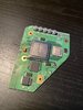
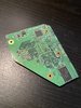
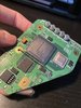
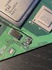
Just finished trimming my Wii's motherboard to start my first portable build. I'm a little worried that I might have cut it a little bit to close, but I'm not sure, let me know what you guys think.
I'm either gonna make an Ashida or a G-boy, and I'm kind of torn, because I know Ashida parts are easier to get ahold of right now, but I really love the form factor of the G-boy.

IMG_2327.JPGIMG_2328.JPGIMG_2329.JPGIMG_2332.JPGIMG_2333.JPG
 
Last edited:

Stitches

2 and a Half Dollarydoos
Staff member
.
.
Joined
Feb 5, 2017
Messages
3,844
Likes
3,023
Location
Banana Bender Land, Australia
Portables
6
Your trim looks good to me, nice bit of margin on the NAND traces, although you lost the one 3.3v cap by the NAND pins. I'm not much a fan of the jacketed U10 wire due to bias against glue, but I see no problems. Just make sure you remove any components on the edge that you hit or cut through, they'll cause shorts and give you a headache later.
 
Joined
Jan 27, 2023
Messages
17
Likes
4
Your trim looks good to me, nice bit of margin on the NAND traces, although you lost the one 3.3v cap by the NAND pins. I'm not much a fan of the jacketed U10 wire due to bias against glue, but I see no problems. Just make sure you remove any components on the edge that you hit or cut through, they'll cause shorts and give you a headache later.
Thanks for the input! Is the 3.3v cap going to need to be relocated? Also, what's your preferred wire choice, I just used what I have from other projects.
 

Stitches

2 and a Half Dollarydoos
Staff member
.
.
Joined
Feb 5, 2017
Messages
3,844
Likes
3,023
Location
Banana Bender Land, Australia
Portables
6
Thanks for the input! Is the 3.3v cap going to need to be relocated? Also, what's your preferred wire choice, I just used what I have from other projects.
It can survive without the cap, but the 3.3v feed that was in line with the cap may need relocation. See the following image:

I can't remember if the voltage pins are connected internally, so it may boot as it is, but I can't say for sure.

For relocations like the U10 and via data connections in general, the recommended wire type is 34-38AWG magnet wire. Good quality 30AWG kynar wire works too, but magnet wire is the best due to its flexibility and low profile. Ultimately any wire will work, and what you have done currently looks good and doesn't need to be changed.
 
Joined
Jan 27, 2023
Messages
17
Likes
4
It can survive without the cap, but the 3.3v feed that was in line with the cap may need relocation. See the following image:

I can't remember if the voltage pins are connected internally, so it may boot as it is, but I can't say for sure.

For relocations like the U10 and via data connections in general, the recommended wire type is 34-38AWG magnet wire. Good quality 30AWG kynar wire works too, but magnet wire is the best due to its flexibility and low profile. Ultimately any wire will work, and what you have done currently looks good and doesn't need to be changed.
Awesome, thanks for the help! Once a few parts arrive I guess I'll see if it boots.
 

Stitches

2 and a Half Dollarydoos
Staff member
.
.
Joined
Feb 5, 2017
Messages
3,844
Likes
3,023
Location
Banana Bender Land, Australia
Portables
6
I forgot to say that the ground connection on the close shave side of the chip will need relocating in addition to the 3.3v connection if it doesn't boot
 
Joined
Jan 27, 2023
Messages
17
Likes
4
I forgot to say that the ground connection on the close shave side of the chip will need relocating in addition to the 3.3v connection if it doesn't boot
Which ground, pin 36? Also for the relocation would you just solder a wire directly to the pin, and then it's corresponding destination? sorry if these questions are kinda basic, I've never really worked with motherboards
 

Stitches

2 and a Half Dollarydoos
Staff member
.
.
Joined
Feb 5, 2017
Messages
3,844
Likes
3,023
Location
Banana Bender Land, Australia
Portables
6
Which ground, pin 36? Also for the relocation would you just solder a wire directly to the pin, and then it's corresponding destination? sorry if these questions are kinda basic, I've never really worked with motherboards
Yeah, pin 36. And yes, you just run a little wire from each of the pins to a spot that has what the pin needs. 3.3v locations are marked in red, and you can get ground from anything attached to the ground plane
 
Joined
Jan 27, 2023
Messages
17
Likes
4
Just got parts from 4layer in the mail, so I'm finally able to test my trim. It seems like it boots, but I'm not the expert here. I put in the USB with all the software downloaded on it, but it still gives me the same screen. Am I missing anything, or is there something else I should test before moving on in the project? Let me know what you guys think.

IMG_3106.JPG
IMG_3110.JPG
IMG_3107.JPG
 

Stitches

2 and a Half Dollarydoos
Staff member
.
.
Joined
Feb 5, 2017
Messages
3,844
Likes
3,023
Location
Banana Bender Land, Australia
Portables
6
Just got parts from 4layer in the mail, so I'm finally able to test my trim. It seems like it boots, but I'm not the expert here. I put in the USB with all the software downloaded on it, but it still gives me the same screen. Am I missing anything, or is there something else I should test before moving on in the project? Let me know what you guys think.

View attachment 26320View attachment 26322View attachment 26321
You haven't wired the USB data lines to the Wii. D+ and D- on the PMS-PD2 need to be wired to the CM1 USB line on the Wii.

Also get those boards out of that conductive metal tin, you're just asking for a short to kill the system
 
Joined
Jan 27, 2023
Messages
17
Likes
4
You haven't wired the USB data lines to the Wii. D+ and D- on the PMS-PD2 need to be wired to the CM1 USB line on the Wii.

Also get those boards out of that conductive metal tin, you're just asking for a short to kill the system
Oh for sure, I didn’t test the board on that tin, thanks for the info on the data line though.
 

Stitches

2 and a Half Dollarydoos
Staff member
.
.
Joined
Feb 5, 2017
Messages
3,844
Likes
3,023
Location
Banana Bender Land, Australia
Portables
6
Oh for sure, I didn’t test the board on that tin, thanks for the info on the data line though.
Btw for reference: Each USB data via pair marked in the Wii Trimming Guide has D+ marked in green and D- is the grey one.
Also the USB data wires are a differential pair, and the wires for D+ and D- must be tightly wound together like a helix to mitigate interference. Failure to do this will result in significant reliability issues and potential boot failure.
 
Last edited:
Joined
Jan 27, 2023
Messages
17
Likes
4
Well, after connecting the data lines I've gotten varied results. I was able to get it to boot to RV loader once, but usually it either boots to the same error screen, or just goes black. I'm aware that my D- wire is not connected in the picture, the solder joint broke when I moved the board. I'll resolder it at some point and test again in case it was my subpar soldering at fault. Is there an easier way to connect up those data lines, or what would you suggest my next course of action is? Thanks for all your help again, you're doing a lot and I appreciate it.
IMG_3222.JPG
 

Stitches

2 and a Half Dollarydoos
Staff member
.
.
Joined
Feb 5, 2017
Messages
3,844
Likes
3,023
Location
Banana Bender Land, Australia
Portables
6
Well, after connecting the data lines I've gotten varied results. I was able to get it to boot to RV loader once, but usually it either boots to the same error screen, or just goes black. I'm aware that my D- wire is not connected in the picture, the solder joint broke when I moved the board. I'll resolder it at some point and test again in case it was my subpar soldering at fault. Is there an easier way to connect up those data lines, or what would you suggest my next course of action is? Thanks for all your help again, you're doing a lot and I appreciate it.
View attachment 26345
Solder the wires to the vias instead. It's easier and you don't need the CM components when using a PMS-PD2
 

Benge

.
Joined
May 18, 2020
Messages
203
Likes
694
Location
France
Portables
4 : O-Wii (V1,V2,V2.1)/ BS2
Well, after connecting the data lines I've gotten varied results. I was able to get it to boot to RV loader once, but usually it either boots to the same error screen, or just goes black. I'm aware that my D- wire is not connected in the picture, the solder joint broke when I moved the board. I'll resolder it at some point and test again in case it was my subpar soldering at fault. Is there an easier way to connect up those data lines, or what would you suggest my next course of action is? Thanks for all your help again, you're doing a lot and I appreciate it.
View attachment 26345
A tip: use the holy enameled copper wire for small vias, it's much more easy, and with this you don't risk to break the solder or worse the vias or the track by moving the wire.
0.1 to 0.15mm work well for signal wire, bigger is too rigid.

Of course before soldering it is necessary to tin the wire to make leave the enamel, it is also faster than stripping a normal wire and then tinning it.
 
Top