- Joined
- Oct 6, 2021
- Messages
- 26
- Likes
- 29
Hello, I need a little help with a data line demultiplexer in my Wii. So I've got a dock that goes along with the portable and whenever the system is docked it should switch the player one data line from the internal controls to the controller port held inside the dock. I already had some PCB's made up and an IC picked out to do the switching but when I had everything wired up my controls weren't working at all.
I wired my GC+ board to a controller plug and tested it with my Gamecube and ensured that my GC+ board was actually working. I also wired up a Gamecube controller to my Wii to verify that nothing was broken on the Wii side of things and I was able to use that controller just fine. So I narrowed it down to something between the Wii and my GC+ board which could only be an FFC I have connecting the boards or the demux that the data line goes through. I tested continuity through the FFC and that seemed fine so I'm assuming that it's the demux at this point.
The demux I had chosen for my design is this one and my design goes something like this -
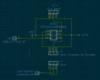
The 3v3 and Select pins are bridged on the dock side thus providing 3v3 along the Select line when the system is docked.
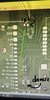
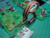
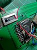
Is there anything inherently wrong with my design or my IC choice? Any help would be greatly appreciated! Here's a few other pics of the physical design as well.
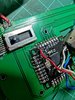
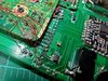
I know I've got duplicate wires and a few things are a little messy. This is just because I was trying a ton of stuff while troubleshooting the issue and doesn't reflect how I currently have it wired exactly. At the moment I've got 1 wire for the data line from the Wii to the board next to it, then another wire from there straight to the GC+ completely bypassing the demux and FFC for the data line. I also thought that maybe I put the demux on backwards and that's why it wasn't working so I tried reversing it and then it started smoking haha. I'm guessing I'll need to replace it but I wanted to get some help with the issue before that.
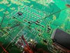
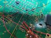
One last thing that I noticed also was that when I ran a data line straight to the GC+, even that wasn't working until I cut this trace here leading back to the demux.
And that's basically all I've got. Hopefully that was thorough enough and someone would be able to help me. Thanks in advance!
I wired my GC+ board to a controller plug and tested it with my Gamecube and ensured that my GC+ board was actually working. I also wired up a Gamecube controller to my Wii to verify that nothing was broken on the Wii side of things and I was able to use that controller just fine. So I narrowed it down to something between the Wii and my GC+ board which could only be an FFC I have connecting the boards or the demux that the data line goes through. I tested continuity through the FFC and that seemed fine so I'm assuming that it's the demux at this point.
The demux I had chosen for my design is this one and my design goes something like this -
The 3v3 and Select pins are bridged on the dock side thus providing 3v3 along the Select line when the system is docked.
Is there anything inherently wrong with my design or my IC choice? Any help would be greatly appreciated! Here's a few other pics of the physical design as well.
I know I've got duplicate wires and a few things are a little messy. This is just because I was trying a ton of stuff while troubleshooting the issue and doesn't reflect how I currently have it wired exactly. At the moment I've got 1 wire for the data line from the Wii to the board next to it, then another wire from there straight to the GC+ completely bypassing the demux and FFC for the data line. I also thought that maybe I put the demux on backwards and that's why it wasn't working so I tried reversing it and then it started smoking haha. I'm guessing I'll need to replace it but I wanted to get some help with the issue before that.
One last thing that I noticed also was that when I ran a data line straight to the GC+, even that wasn't working until I cut this trace here leading back to the demux.
And that's basically all I've got. Hopefully that was thorough enough and someone would be able to help me. Thanks in advance!