Question Help with circuit for cutting power to screen when docked

Joined
Oct 6, 2021
Messages
26
Likes
29
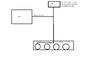
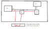
Hello, I'm currently working on my second portable and I wanted to challenge myself to make my own PCB's for this build. Basically I'm making a Wii portable and I want it to have a dock that has an HDMI out port on it. When the system is docked I want to turn the screen off and cut off all audio from the handheld itself. My idea I have to accomplish this is to just cut off the 3V3 power source to both the screen and the U-amp board that I am using but I'm having a little trouble designing a circuit that is normally closed and then becomes open when the system is docked.

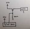
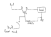
Could I simply just use an N-channel depletion type mosfet for this purpose? I would have the 3V3 line going through the mosfet from source to drain and then when the system is docked a power line would come from the dock to activate the gate on the mosfet thus breaking the circuit to the U-amp. If I did do this, would I need any other passive components or would just a mosfet suffice?

And if the Mosfet thing wouldn't work, would an IC like the TPS2024 or BD82042FVJ work in it's stead?

Any help would really mean a lot as I don't have any experience in designing circuits and I've had a bit of a hard time figuring out this specific issue.

Also, here's the links to the 2 IC's mentioned above -
 

Attachments

YveltalGriffin

First Wii U Trimmer
.
Joined
Jun 7, 2016
Messages
308
Likes
1,162
Location
South Florida
Portables
5
For high-side switching like this, you should probably stick with an enhancement-mode P-channel FET. Add a pulldown resistor in the range of 1k - 100kohms to the gate to make it "on" by default, and then have your dock connect the gate directly to 3.3v to turn it off.

IMG_20220119_001220~2.jpg

Just make sure you select a FET that has a low enough Vgsth to turn on fully at Vgs = 3.3V, and has plenty of continuous drain current headroom for the full load you'll be passing through it. A quick search on Mouser shows tons of 3A+ p-channels in easy-to-solder packages like SOT23 and TSOP that would work well.
 
Joined
Oct 6, 2021
Messages
26
Likes
29
For high-side switching like this, you should probably stick with an enhancement-mode P-channel FET. Add a pulldown resistor in the range of 1k - 100kohms to the gate to make it "on" by default, and then have your dock connect the gate directly to 3.3v to turn it off.

View attachment 20836

Just make sure you select a FET that has a low enough Vgsth to turn on fully at Vgs = 3.3V, and has plenty of continuous drain current headroom for the full load you'll be passing through it. A quick search on Mouser shows tons of 3A+ p-channels in easy-to-solder packages like SOT23 and TSOP that would work well.
Thank you so much for the reply! I'll probably go forward with this approach then but I just wanted to make sure I understand it correctly. The MOSFET in your example would normally be off but because of the resistor connecting it to ground it's supplied a sufficient negative voltage to turn on, right?

I also had one more follow-up question to this. On the dock I will have gamecube controller ports and I want to switch the Player one data line from the internal GC+ to the external controller port when docked. I could use some kind of mux to switch between the two easily enough but since I will already be cutting 3v3 to some of the other components when docked, could I just have the data line split to connect both to the GC+ and the dock at the same time and then just cut power to the GC+ so it would be ignored? Or would using some kind of switch between the two be better?
 

Attachments

YveltalGriffin

First Wii U Trimmer
.
Joined
Jun 7, 2016
Messages
308
Likes
1,162
Location
South Florida
Portables
5
The MOSFET in your example would normally be off but because of the resistor connecting it to ground it's supplied a sufficient negative voltage to turn on, right?
Yep, P-channels turn on when the voltage on the gate is negative with respect to the source voltage.

I would use a mux for the controller data line, since you don't want the external controller to 'phantom power' the GC+ through its GPIO.
 
Joined
Oct 6, 2021
Messages
26
Likes
29
Yep, P-channels turn on when the voltage on the gate is negative with respect to the source voltage.

I would use a mux for the controller data line, since you don't want the external controller to 'phantom power' the GC+ through its GPIO.
So I finally got my PCB's in using this circuit design and I'm not sure if I just got a mosfet that isn't suitable or if I messed something else up. The mosfet I purchased is this one (I also got this one as a backup). And my circuit looks something like this -

1645577621239.png

So it looks like I'm able open (close?) the gate just fine. With no input voltage from the dock and using the pull-down resistor I am able to get 3v3 to the load. But when I supply the dock voltage to the gate I still get a voltage reading of around 3v at the source pin where I would expect to get no voltage. I have also tried supplying 5v instead of 3v3 from the dock but I still get a voltage reading of around 2.8v at the source pin.

My guesses for what the issue would be are either
- that I need a mosfet with some different specs as this one isn't suitable with the wanted voltages
- or that the drain and source pins need to be reversed in my schematic

Any help is always appreciated. Thanks in advance!
 
Top