Fan Not Turning On (Step 7)

Joined
Apr 12, 2020
Messages
131
Likes
260
Hi Folks,

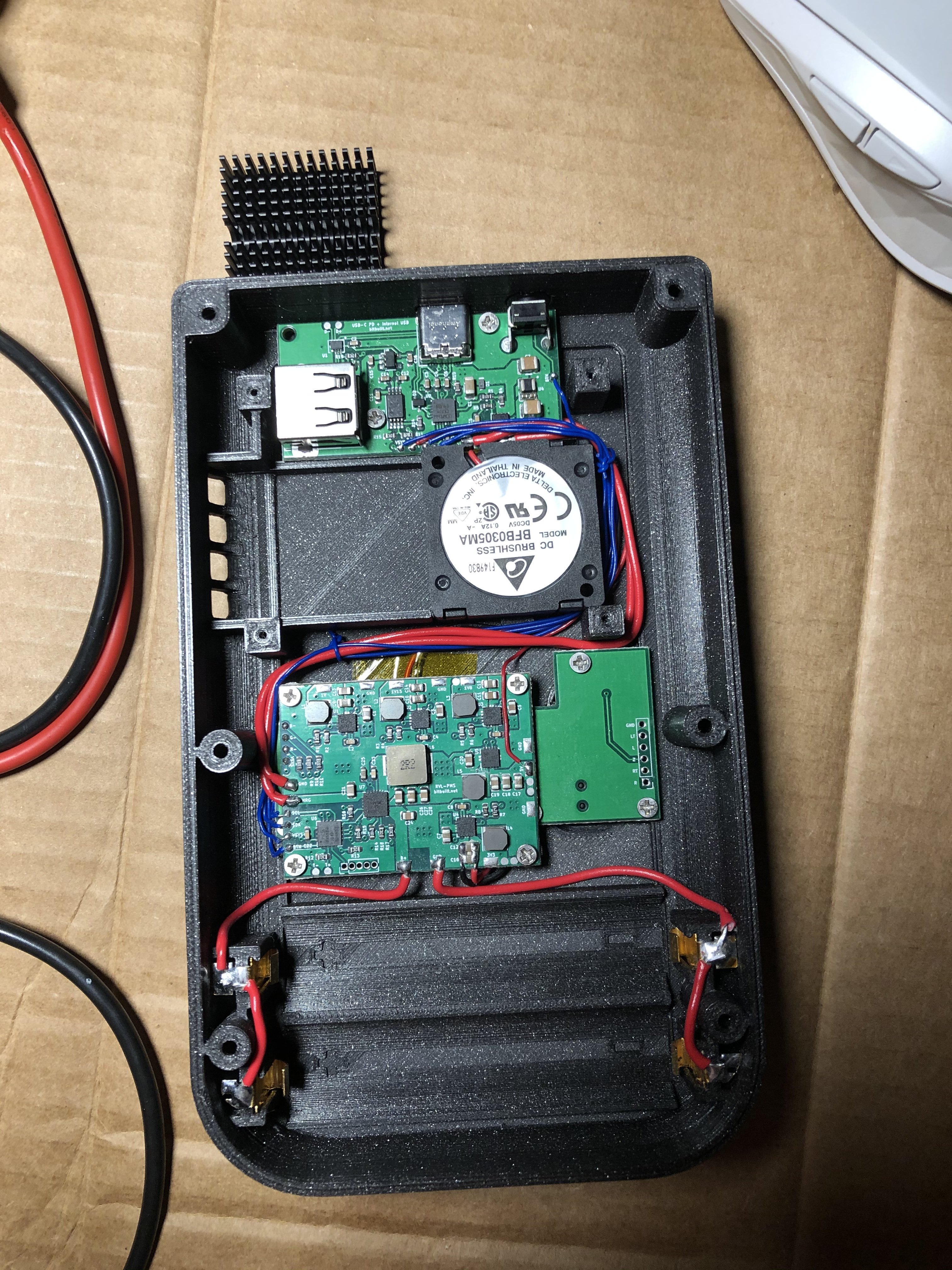
I finished step 7 of the guide (wiring the USB-C PCB) but I have not been able to turn on the fan. The (1) battery is 3.73v to the PMS and I checked for continuity across all my wires and everything checked out. I saw that the manual is for the old PMS, so I have nothing visual to compare it to. I checked the 3.3v and 5v pads and they both didnt show any power going to them. Any suggestions? Is there anyway the device is in "shipping mode" and did I wire to the correct "VSYS"? Photo attached and I wasnt able to sync to the wiiboy build discord (my phone wouldnt recognize the QR code)
4D36DB85-D9C8-4E21-9540-46E01E221B71.jpeg
 
Last edited:

Noah

retired
.
.
Joined
Jan 16, 2016
Messages
1,968
Likes
2,567
Location
The World Wide Web
Portables
Had you powered on the G-Boy when the wires were flipped before Gman pointed it out?

Yes VSYS is wired correctly. The new PMS has a dedicated pad for it which is used for the USB-C board and the RGB LED. We'll be releasing the update to the manual this weekend for the new RVL-PMS PCB.

I would remove the fan wires and try turning it on again. You should be getting voltage across all of the pads on the top as well as the 5V and 3.3V pads. Once you remove the battery and reinsert it shipping mode would be disabled if it were enabled beforehand.

I will also send you a PM with the invite to the discord server.
 
Joined
Apr 12, 2020
Messages
131
Likes
260
Had you powered on the G-Boy when the wires were flipped before Gman pointed it out?

Yes VSYS is wired correctly. The new PMS has a dedicated pad for it which is used for the USB-C board and the RGB LED. We'll be releasing the update to the manual this weekend for the new RVL-PMS PCB.

I would remove the fan wires and try turning it on again. You should be getting voltage across all of the pads on the top as well as the 5V and 3.3V pads. Once you remove the battery and reinsert it shipping mode would be disabled if it were enabled beforehand.

I will also send you a PM with the invite to the discord server.
Thanks for the prompt response, Noah. I did not insert the battery or turn on the unit until after I corrected the wiring per gman's instructions. Nor did I smell or hear anything when I attempted to turn it on (Battery was also facing the correct way). I will disconnect the fan wires and see if anything changes and report back.
 
Joined
Apr 12, 2020
Messages
131
Likes
260
Alright, so I disconnected the fan and removed the bridges between c12 and c16. No dice. I took some voltage readings hoping it might help pin point the problem.

PMS
BTN C22 (PMS) 3.729v
VSYS (PMS) 3.73v
SDA (PMS) 0.29v
SCL (PMS) 0.18v
3v3 (PMS) 0.0v
5v (PMS) 0.0v

USB-C
BTN (USB-C) 3.729v
VSYS (USB-C) 3.73v
SDA (USB-C) 0.29v
SCL (USB-C) 0.18v
5v (USB-C) 0.0v

All grounds have continuity*
 

Gman

RTFDS
Staff member
.
.
.
.
.
Joined
Feb 25, 2016
Messages
1,437
Likes
2,887
Vsys voltage present, GOOD. This is indicator that the PMS is most likely not shorted, let's keep it that way. Most importantly be extremely careful when you test it and use the probes. Couple people before have killed their PMS by accidentally crossing the probes or shorting something with them.

Just clearing up, you are holding down the power button for 1-2 seconds? This is how to turn it on.

With batteries out, I would check continuity between all the pads to verify that each one is going to the right place on the usbc board.

Sda and scl are i2c communication lines so you won't be able to accurately measure them with the multimeter. They should be idle high although it's possible you measure during a transmission which would make the voltage on the meter different.
 
Joined
Apr 12, 2020
Messages
131
Likes
260
Vsys voltage present, GOOD. This is indicator that the PMS is most likely not shorted, let's keep it that way. Most importantly be extremely careful when you test it and use the probes. Couple people before have killed their PMS by accidentally crossing the probes or shorting something with them.

Just clearing up, you are holding down the power button for 1-2 seconds? This is how to turn it on.

With batteries out, I would check continuity between all the pads to verify that each one is going to the right place on the usbc board.

Sda and scl are i2c communication lines so you won't be able to accurately measure them with the multimeter. They should be idle high although it's possible you measure during a transmission which would make the voltage on the meter different.
Yes, I have tried holding the power button for varying intervals from 1-5 seconds without any different results.

I have been very careful not to miss-probe any connects, as I am aware of what can happen. I just ran a continuity test on all pads and connections again (with batteries out) and everything passed. Mhmmm,a head-scratcher for sure. Looks like I need to follow the power until I find something a-miss. Any suggestions?
 

Gman

RTFDS
Staff member
.
.
.
.
.
Joined
Feb 25, 2016
Messages
1,437
Likes
2,887
What happens when you connect a charger? Do you measure any voltage on the charge pad?

Best thing to do in troubleshooting is going back to the basics. Disconnect the wires except for the battery, then button and ground to the usbc board. This will isolate the usbc board and see if you can get just the PMS working.
 
Joined
Apr 12, 2020
Messages
131
Likes
260
Just plugged in the old charger and was getting 5.18v to the charge pad on the PMS.

I will try your recommendation and report back! Appreciate the help as always.
 
Joined
Apr 12, 2020
Messages
131
Likes
260
So I disconnected everything and made some jumper wires to BTN and Ground from the USB-C to the PMS. I powered it up and had nominal voltages across 3.3v and 5v pads. So it looks like the PMS is in good shape. With that said, would indicate I just wired it incorrectly? Or does further testing need to be done on the USB-C?
 

Gman

RTFDS
Staff member
.
.
.
.
.
Joined
Feb 25, 2016
Messages
1,437
Likes
2,887
So I disconnected everything and made some jumper wires to BTN and Ground from the USB-C to the PMS. I powered it up and had nominal voltages across 3.3v and 5v pads. So it looks like the PMS is in good shape. With that said, would indicate I just wired it incorrectly? Or does further testing need to be done on the USB-C?
That's great progress! Um its possible sure. I guess try again with great detail.

If you suspect something, you can wire it up one section at a time. So next you could wire scl, sda, and vsys. Then add 5v, then charge. If it stops working along the steps, then you know where to look.
 
Joined
Apr 12, 2020
Messages
131
Likes
260
Alright, so I redid all the wiring and was able to pin-point the issue. Whenever I wire up SCL or SDA independently or together the board stops supplying power to the 3.3v or 5v pads respectively. I tried doing a jumper wire without routing the wires to both and still the same issue. If I disconnect both SCL and SDA the fan turns on fine. No lifted pads or anything and I made sure ground had a nice full coverage of solder. Any input?
 

Gman

RTFDS
Staff member
.
.
.
.
.
Joined
Feb 25, 2016
Messages
1,437
Likes
2,887
I tried doing a jumper wire without routing the wires to both and still the same issue.
I'm not sure what this means.

Huh ok interesting. I'm curious to see the result when you wire up the rgb led. The led status will give some extra insight into what the PMS is doing and if it is working properly.

Making sure, sda and scl wires are not swapped on the usbc board?
 
Joined
Apr 12, 2020
Messages
131
Likes
260
By "jumper", I just mean I grabbed some new wires and didnt feed them under the fan. Same results. I have verified the sda and scl aren't swapped. Ill wire up the LED and see what the blink codes are.
 
Joined
Apr 12, 2020
Messages
131
Likes
260
Alright, just finished wiring up the led. It doesnt come on when scl and sda are plugged in (confirmed they are not swapped)...if I disconnect them I get a solid green light until I power down.
214848C0-D644-48BF-AF1E-53613696F084.jpeg
 

Gman

RTFDS
Staff member
.
.
.
.
.
Joined
Feb 25, 2016
Messages
1,437
Likes
2,887
Ok good. If you double tap the button, it should change between led statuses too. Check if scl and sda are shorted on the usbc board. Could you take a close up picture of the usbc board circuitry?
 
Joined
Apr 12, 2020
Messages
131
Likes
260
Is it possible that VSYS is shorted to ground on the USBC board?
Thanks for your input! Nope, I just checked the wiring. No breaks in the wiring that would cause it to short with ground.


Ok good. If you double tap the button, it should change between led statuses too. Check if scl and sda are shorted on the usbc board. Could you take a close up picture of the usbc board circuitry?
I was able to get the led to cycle through different modes as well. Groovy colors on that one mode hahaz

I checked for shorts, none to report. I switched to color-coated wiring to help with troubleshooting. Here is a picture of the usbc.

E95415BD-6488-4644-B2CC-EF145F6A010D.jpeg
 

Gman

RTFDS
Staff member
.
.
.
.
.
Joined
Feb 25, 2016
Messages
1,437
Likes
2,887
If the led is green in battery mode, that means the sda scl is working on the rvlpms. Not sure what's going on with the usbc wiring. The sda and scl to the usbc is only for power delivery charging negotiation. By default without the wires connected, it will work with 12v2a, 9v3a, or 5v if the first two do not match the charger. I use 9v3a charger so the negotiation isn't any benefit there. Maybe you figure it out later, but not connecting those two wires won't affect the functionality as long. Let's see if the usb part works on the later steps. If you put the sd card in the board, then connect usbc to the computer, with the gboy off, the drive should pop up on the computer.
 
Joined
Apr 12, 2020
Messages
131
Likes
260
Thanks for the input, gman. For charging bricks, I have one that does 9v2a and another that does 5v2a. So ill probably use the former. I only had a usbc cable without a data line (stupid oculus quest) :p. Waiting on the cable in the mail. Should be here by tomorrow. Ill update then or the next day.
 
Last edited:
Joined
Apr 12, 2020
Messages
131
Likes
260
Alright, so I tried a few things with the usbc. I got the recommended Anker cable with data transmission.

Inserted the usb to micro SD card adapter (noting the correct orientation)with a micro sd card (samsung evo 125gb). Plugged the usbc cable into a data port on my pc and the other end into the g-boy with it turned off. I got an alternating green and red light blinking sequence on the led:

Solid green (4seconds)
Solid red (1/2 sec)
Solid green 4seconds)
Solid red (1/2 sec)
2 green blinks
Etc.

My computer did not recognize a new drive....I tried another SD card and putting batteries in and the led changed to charging mode (rolling red on the led). I tried switching to 3 different usbc ports on my computer and all of them didnt recognize the sd card. Lastly, I soldered on slc and sda again and of course, the fan and led werent getting any power. Any suggestions?
 
Top