
I've been working on designing my own PCB for an N64 controller for a little bit now, similar idea to the famous RDC chip that Downing uses in his portables. I know there is an N64+ controller chip coming soon thanks to the great work of some of the folks on these forums, but I'm using this as an exercise for myself in bolstering my EAGLE skills, and I won't lie it's really fun as well.
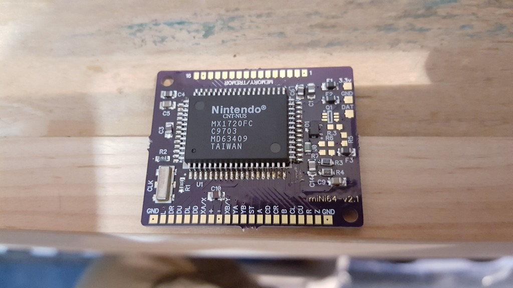
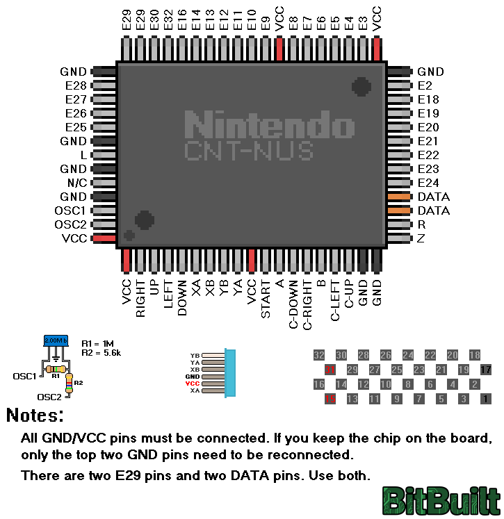
In my process I've been wondering what components really are necessary to get the CNT-NUS chip to work. From the official controller chip pinout thread I know that the OSC 1 and 2 must be connected to their respective 5.6k and 1M resistors and then to the CLK chip, but what about all of the other capacitors, resistors and fuses?
I see RDC included quite a few of these components in his board, but I keep wondering what components really are necessary... which has led me down a small rabbit hole of determining what the values of each one of these components are and if similar components can be sourced from sites like mouser or digikey.
So here is my progress so far.
Resistors are easy to test, simply check them with the OHM setting on any multimeter, but capacitors are trickier since to get an accurate reading they need to be removed from the PCB. What I've done is desoldered a few capacitors I deemed necessary based off of RDCs board. Using the DC V setting on my multimeter I can touch each lead of the cap and discharge it to 0V, then switching to CAP mode I can then measure the capacitance. Here's what I've found so far:
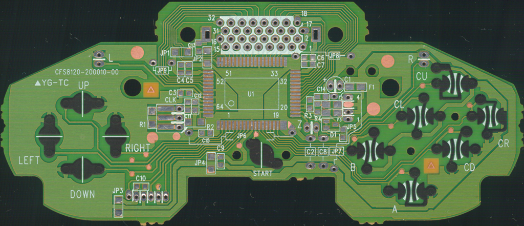
C3 = 1300pF
C4 = 1300pF
C5 = 1050pF
C6 = 0.11uF
C7 = 1200pF
C9 = 1100pF
C10 = 1uF
C14 = 91pF
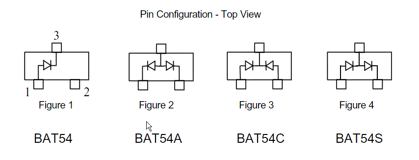
Additionally, D1 is a 3 pin SOT23 diode in the BAT54 configuration, where pin 1 is the anode and 3 is the cathode. From the controller schematic and using the continuity test on my multimeter, it's easily seen that pin 2 is bridged to pin 1.
So this leads me to the discussion... Has anyone else (I guess besides RDC, who doesn't seem active on the forums) gone down this rabbit hole and started trying to measure and record each of the components on the controller? Is there a point to all of this or am I wasting my time? I'd love to discuss this and dig deeper.
In my process I've been wondering what components really are necessary to get the CNT-NUS chip to work. From the official controller chip pinout thread I know that the OSC 1 and 2 must be connected to their respective 5.6k and 1M resistors and then to the CLK chip, but what about all of the other capacitors, resistors and fuses?
I see RDC included quite a few of these components in his board, but I keep wondering what components really are necessary... which has led me down a small rabbit hole of determining what the values of each one of these components are and if similar components can be sourced from sites like mouser or digikey.
So here is my progress so far.
Resistors are easy to test, simply check them with the OHM setting on any multimeter, but capacitors are trickier since to get an accurate reading they need to be removed from the PCB. What I've done is desoldered a few capacitors I deemed necessary based off of RDCs board. Using the DC V setting on my multimeter I can touch each lead of the cap and discharge it to 0V, then switching to CAP mode I can then measure the capacitance. Here's what I've found so far:
C3 = 1300pF
C4 = 1300pF
C5 = 1050pF
C6 = 0.11uF
C7 = 1200pF
C9 = 1100pF
C10 = 1uF
C14 = 91pF
Additionally, D1 is a 3 pin SOT23 diode in the BAT54 configuration, where pin 1 is the anode and 3 is the cathode. From the controller schematic and using the continuity test on my multimeter, it's easily seen that pin 2 is bridged to pin 1.
So this leads me to the discussion... Has anyone else (I guess besides RDC, who doesn't seem active on the forums) gone down this rabbit hole and started trying to measure and record each of the components on the controller? Is there a point to all of this or am I wasting my time? I'd love to discuss this and dig deeper.
 It was still fun!