- Joined
- Dec 31, 2022
- Messages
- 61
- Likes
- 84
- Portables
- 2 (Ashida & Xii-Boy Ultra)
We're in the homestretch now! So glad to see all your hard work paying off. Congrats Xenii! 
Holy crap I am so excited for this to be ready to build this is crazy work that you managed to pull it off with no wires!Hey there!
It was time: Welcome to the episode #6!
I have some crazy progress to show you, I hope you'll like this episode!
A few days after the last post, I received everything I needed to continue this project!
However, itt was only missing one thing: the 4LayerTech stuff. It was clearly the package I waited the most!
During that time, I decided to assemble the custom PCBs!
Starting with the simplest: The Xii-Strip!
View attachment 38200
Well, it only has one thermistor, so it was pretty fast and easy to assemble
I then started the second PCB: The Trigger PCB!
View attachment 38197
I decided to use my mini hot plate to save some time. It was the first time I used it, and it went well!
After some little reflow on the connectors, it was done!
View attachment 38198View attachment 38199
I'm very happy of those buttons, they feel fantastic! Thanks @YveltalGriffin for the recommendation!
Next one: Controller PCB!
View attachment 38201View attachment 38202
Unfortunately, it was the first PCB to contain mistakes. The biggest on this board is that I didn't order the proper JST connectors for the speakers.
They used 1.25mm, and by measuring, I got and ordered 1mm of pitch... It's really not a big deal. To correct that, I just ordered new ones on AliExpress, we'll see later how I'll solder them...
Next one: Xii-DD!
It started getting harder. Controller PCB already had the biggest connector I've never soldered: 18 pins.
The biggest connector XB2 uses is only 17 pins. Xii-DD is another level: 40 pins
After some cooking time, and some reflow with my beloved ChipQuick SMD291 flux, It was looking decent!
View attachment 38203
After soldering the easier 18p connector, Xii-DD was done!
View attachment 38204
It was time for the hardest and biggest PCB of the whole project: the Main PCB
View attachment 38205
Starting with those 40 and 50 pins connectors! It went really well! I also soldered the side buttons, and I think they aren't as satisfying as XB2 ones are,
but they feel really good. I really like them!
Cooking done!
View attachment 38206
The hardest was now behind!
Next challenge; the Pogo pins!
View attachment 38208
It wasn't really hard, it was just kinda tricky to make them flat.
After a few hours of soldering, the bad boy was done!
View attachment 38210
It's looking really good!
The testing phase has begun!
I first started the PCM circuit. Battery are charged, I tested the tension between the PMS2 B+ and B- pads, and it got 2.94V...
It seemed really low to me. Battery were around 4.11V, so I guess something is wrong...
I asked @YveltalGriffin for help, and he told me that by default, PCM might be disabled. To activate it, I just had to short B- in and B- on the Mosfet IC for a brief time.
But it still didn't work...
We then noticed that the Mosfet IC was soldered backwards...
I just reversed its orientation, and it worked! Great news!
Actually, to test it, I'd like to short something to get a 4A spike on the batteries. But, doing that is risky, and impossible at that point, still no PMS2 in my mailbox...
I spent approximatively one day and half assembling the board. It was now missing two main things: 4LT, and a trimmed Wii.
So I started hacking a trimming a Wii!
View attachment 38193
View attachment 38194View attachment 38195
Trimming went well! I sanded it and checked the resistances, they were all good!
A few days later, I received the 4LayerTech package!
View attachment 38211
Btw, big thanks to the 4LayerTech team for their great service! The boards are amazing!
I quickly placed them on my PCB to see if they fit well, and they do!
View attachment 38212
First thing I've done was to solder GC+ 2 on the Controller PCB for testing.
I solder a GCC cable to the GC+ 2 and turn on a Wii!
And.... It works perfectly! No mistake here, everything is working fine!
I also had to test the triggers, which are tricky to test on XB3 just because I add to connect all the boards together.
View attachment 38213
After testing all that mess together, it works!
As you can see, I also tested LRA rumble motor, hall effect sticks and the new connectors for the speakers.
Everything works! I just have to really configure rumble once the build will be closed. Those GCC cable wires are super thin, it cannot deliver enough current for the whole boards which causes little issues with rumble.
Next step was to test the Wii motherboard!
View attachment 38214
But after spending hours, I wasn't able to make it boot. I really don't understand, I have a black screen, no booting, U10 is working though...
I tested everything, but it still didn't work. Two days later, still no solutions...
Considering I didn't have a lot of free time, I decided to trim another Wii and spending time later on that trim.
3 hours later, the second trim was done, sanded, and the resistances have been checked.
This one boots! YAY!!!
View attachment 38215
It was finally time to test everything together.
I first had to solder the required stuff on the trimmed Wii.
Starting with the Xii-Strip!
View attachment 38216
However, I quickly noticed that it won't be possible... The mistake is really stupid: I designed it in 1.6mm thick, which makes the board impossible to solder.
I couldn't reorder board, so I had to find a solution. Wires? NO WAY!!!
My solution is stupid and dump, but I didn't find better...
I simply used solder wick...
View attachment 38217View attachment 38218
View attachment 38219
Well, it's a really stupid idea. It looks like garbage. But, it works, and I didn't have a better solution.
No worries, though, final revision will correct that. The Pogo pins exist in a taller version, and Xii-Strip just has to be ordered thinner.
You already saw it, but I also soldered the Xii-Strip Ultra!
I first scratched and tinned the vias:
View attachment 38220
And finally put and solder the flex!
View attachment 38222
I then checked all the video connections between the flex and the AVE pins.
View attachment 38223
After some reflow, it was good!
Bluetooth is also attached to the flex but soldered on the other side.
It was pretty easy to solder. I thought it would be harder.
Anyway, here is the final result!
View attachment 38224
View attachment 38225
It looks gorgeous!
Final step: Soldering 4LT stuff on my remaining PCBs.
Here is the Main PCB finally done!
View attachment 38227
After some cleaning, I just corrected a little mistake on that board as well.
View attachment 38229
I didn't connect PMS-PD3 properly. I used normal 5V instead of the UP 5V.
Technically, it works as well while the console is on, but we can't access the data when the console if off.
Correction done, it's time to finally test Wii + Xii-Flex + Xii-Strip + Main PCB!!!
View attachment 38228
I was really stressed. I took my courage, inserted the battery, press the power button, and...
Nothing...
LED even didn't turn on... What is going on? What did I do wrong? I was really confused and lost.
After chatting with @SimplyStevii, they told me LED wasn't set in addressable by default in RVLoader.
Ok so this explains why LED didn't turn on.
It still doesn't explain why video doesn't work.
After the classic troubleshooting tests, I thought: Maybe the Xii-Flex was causing some impedance discontinuities by making some stubs, or kinda antennas.
To test my theory, I had to connect the Xii-DD.
At this point, I thought the project was dead. I wasn't scared of testing DD, I was really testing just in case, I didn't hope anything...
View attachment 38230
And as planned: nothing...
I started checking every solder, every contact between DD and the AVE through all my mess, but still nothing.
And by looking on the 4LT website, I noticed that my screen was plugged backwards...
Holy moly, it was frustrating, but it might not be dead.
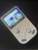
I had hope. I plugged the screen in the correct orientation, turn the Xii-Boy 3 on, and...
View attachment 38231
HOLY MOLY!!!!
I didn't expect it to work anymore. You cannot imagine how much I screamed of joy after that
To retest my theory of impedance discontinuities, I then soldered composite video again.
But still nothing. After asking @YveltalGriffin, he didn't believe in my impedance theory.
Considering Yveltal is always right, I asked him if he had any ideas of what's going on.
And then, he answered me:
View attachment 38232
Well, yup, it was only that. Xii-Flex hardwires 3.3V to mode. Considering I did enable VGA on this Wii, it just disabled composite and enabled VGA.
I felt stupid, but happy at the same time.
It was time to continue the test process!
Bluetooth first!
View attachment 38233
YAY!
I basically tested everything, and everything works!
Fan, WiFi, Audio, Controls, Screen, everything!
Huge thanks to @Aurelio who took a lot of his precious time to make brightness and volume over buttons working!
It's truly amazing and works extremely well. (I don't have any videos or images though)
I did then work on the case. I printed some final cases, and everything fits well!
View attachment 38234
To sum up: Everything has been tested. Everything works.
It's truly amazing, and it makes me really happy.
I'm happy that the most complex board I've never designed works almost first try!
I can't believe it!
XB3 will need some little corrections like adding a mode jump on the Xii-Flex, reducing the Xii-Strip thickness, correcting the Controller PCB JSTs, correcting the Main PCB about the UP pad, etc. But I mean for a first try of making wire free possible, I think it's an amazing milestone reached!
So, what's left to do?
It's what I'm currently working on: finishing the small things on the shell and order it through JLC3DP!
View attachment 38235
I also modified how the screen is fixed. I added a little "lip" to mimic the FMD layers that stuck the screen in place.
I hope everything will come together nicely!
I'll probably order that this week, but I already want to say that XB3 is almost there!
I think it's all for that episode!
Next one will probably be the last. I hope you're hipped as much as I am!
Thanks a lot to:
@Aurelio for the RVLoader modifications for XB3
@YveltalGriffin and @SimplyStevii for the help about PCB, settings, and other
@supertazon and @Bryceshaw06 for the general help
and everyone else who helped or motivated me!
I'm very glad of seeing that what I'm doing is liked! It makes me really happy. Thanks a lot for all your support
I hope you liked this episode!
Have a wonderful day, and see you very soon!
Thanks!Holy crap I am so excited for this to be ready to build this is crazy work that you managed to pull it off with no wires!
Btw what soldering paste did you use because I really wanted to build this portable myself when it is ready?
")


Very excited for this kit! I was hoping there would be something like this eventually, and you did it you madlad. i want to build this one day and was wondering what the kit would include and the price!Hello everyone!
Welcome to the episode Xii-Boy Ultra Kit #1!
The Xii-Boy Ultra has been released a few months ago, and I thought it would be good to give a little update to that Worklog.
If you read some messages I posted in the BitBuilt Discord Server, or here directly, you might have seen that I mentioned multiple times a story of a "Xii-Boy Ultra Kit". After that, I received practically every single week questions about when it would come out, and at which price. So I thought I should talk about it today.
After the release of the Xii-Boy Ultra, I worked away from modding. I needed to do something different, and needed to earn a bit of money for the future projects.
I found a little job, that I've been working on for a few months. Hopefully, I finished it a few weeks ago, so I was happy to really work again on that kit.
Let's talk about the kit!
The first step was to correct everything that needed to be corrected. I mean by that little issue of the shell, buttons, or PCBs.
I'd like to give a huge thanks to @Bryceshaw06 who took a lot of time for giving me feedback all along the build. 90% of the update I've made are with his help!
I suggest you to read his Worklog to know pretty much all the issues he had. I'll only be talking of some issue and show what I did to correct it.
First, I also wanted to say that most of the issues he had were just due to the early PCB revision I sent him. Most of them have already been fixed since.
ISSUE #1: BATTERY TABS
Since the Xii-Boy Ultra is WireFree, the batteries are connected with battery tabs to the Main PCB. When I received my PCB, the tabs really didn't fit well. It was really hard to install them. Once they were installed and soldered, you needed to bend them with pliers and then unbend them at the tip to make connection.
It was really tricky, but was working fine on my side. However, Bryce spent a huge amount of time to make them work. So I looked for new tabs. After hours of searching, I found those!
View attachment 39753View attachment 39754
You can see the gold one was higher, and also not deep enough to make proper connection with the cells. On the right picture, you can see them that they are way better aligned with the cells. We still need to bend them once, but it should be much better now.
Hope this will be solved!
ISSUE #2: Xii-Strip Pogo
My Xii-Boy Ultra and the current GitHub BETA revision uses Pogo pins to power the Wii using a Xii-Strip.
This system was extremely easy to install, and seemed to be a great solution!
However, Bryce told me they were pretty hard to solder onto the Main PCB.
Then, he had a more important issue. The Wii was constantly crashing if we didn't push on the Wii motherboard where the Pogo pins were.
The issue is caused by the Xii-Strip being HASL and not ENIG. This means instead of being cover by gold which does not oxide over time, it was covered by Leaded HASL, which oxides really quickly. The result were that his Xii-Strip was already oxidized and didn't make proper connection with the Pogos.
I had that issue as well, but since it looked like crashes, I just thought it was USB
This problem is fixable by just using ENIG surface finish on the Xii-Strip.
However, I didn't really enjoy that idea. After thinking more, I thought Pogos were unadapted for that use. The Wii motherboard does not have screw posts on each sides of the Xii-Strip, resulting in contact issue.
Since I was not a fan of Pogos, and I wanted to definitively get rid of the issue, I decided to replace Pogos by a PicoLock cable. Still WireFree, but way more reliable.
In that time, antoineok finds out the Xii-Strip was too thin near the 3.3V area, and could easily shake and break during manufacturing. Once again, to solve that, I simply connected the 3.3V part to the main one, making the strip stronger than it's ever been!! View attachment 39755
Since the Wii had a screw post here, I just kept the screw hole, and made the screw post in the shell 0.8mm shorter.
This will also make the Wii easier to test, since we won't need to screw the motherboard in place to power it!
ISSUE #3: Shell's Button
To make the build easier to assemble, Bryce suggested me to add notches on every button of the design. This prevents them to be inserted backwards, and also make them more stable!
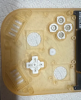
I first added notches for the Z triggers, as well as letter for orientation!
View attachment 39756
Following by the Power and Sync buttons!
View attachment 39757
And finally, the Volume and Brightness buttons!
View attachment 39758
ISSUE #4: Small issues and final polishing
I also spend time upgrading pretty much every part of the design.
The PCBs have been upgraded to rounded, which is better for high frequencies, and also way more beautiful!!
View attachment 39759
I also corrected the issue of bending the Shielded Flex at a 90 degrees angle to install it. Should be way better now
The shell also received some little updates, and everything is now better thanks to Bryce.
Please take note that some of the changes are not available now on my GitHub, since they deserve some testing.
Now, let's talk about the kit!!
So first, yes, the kit is still something I'm working on.
I first searched a lot about the administrative side of the project. How to make an online shop, how to ship packages, etc.
Those were all the questions I was wondering about. I'm not going to explain everything I searched, since it's extremely boring.
But to make things quick though, I've planned making a Shopify website where I could sell my kits.
I also tested shipping packages to multiple countries to get familiar with the custom declaration, and shipping in general.
I tested sending packages to France, the United States and Canada, and all went extremely well and pretty fast (~10 days)
Thanks a lot to the people who received my package! Learned a lot from it!
The issue I was now facing was pretty simple, what do I need to upgrade? I already worked a lot on the design, but what could we upgrade even more to reach perfection?
There is no answer to that, or at least, not yet.
My idea is pretty simple: produce and sell 5 Beta Kits to multiple person on the community, and get their feedback.
I won't share the name of the 5 people I chose, but free to them to talk about it or make Worklogs when they will receive it
Also, one more thanks to Bryce who is working a lot on the upcoming guide the kit will need. The work spent here is huge, and truly perfect.
So what's next to do?
The next step is ordering everything for the five beta kits, assemble each boards by hands (no PCBA for the moment) and package them.
I'm just waiting for some little details, but ordering will be soon!
I'm also contacting companies to get special order, like a custom size copper plate for the cooling system for example, which takes a lot of time. Just need to know exactly what I'm buying before ordering.
Since the goal of the Beta revision is having feedback, the price does almost not include bargains.
This means, Beta and Final kit prices won't be the same. So for the moment, I don't have the exact price of the final kit, thanks for your understanding.
I do know how much I want the kit to be sold, but I'm not sure if I'll be able to keep those prices, especially now, since Trump added a new huge tariff of 39% on Switzerland, and I don't know how much it will impact shipping.
I'll keep everyone updated here.
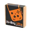
Finally, I'm also collaborating with @JamesPi to design multiple box for the kit. We're experiencing multiple ideas, and see which one will look the best.
I made one myself, which looks good in my opinion, but we need to see if this will be the final design or if we find something even cooler.
To give you something to see for the months I didn't give updates, here is the prototype of the Xii-Boy Ultra Kit Beta box I've designed!!!
View attachment 39764
What do you think about it?
That's all for this time! I'll get everyond updated here! Stay tuned!
SPECIAL THANKS!
- @Bryceshaw06 for the guide and all the feedback
- @JamesPi for the work on box designs
- @YveltalGriffin for the help, advice and PCB review
- @Aurelio for the help with software issues
- @supertazon and @SimplyStevii for the general help
Thanks for reading, have a nice day, and see you next time!
Hi!Very excited for this kit! I was hoping there would be something like this eventually, and you did it you madlad. i want to build this one day and was wondering what the kit would include and the price!
LETSGOOOOOOOOOOHi!
First of all thanks for your support! I really appreciate
I have planned to release a new worklog episode tomorrow or Saturday, since there are some updates I wanted to talk about.
I’ll also talk about delay, production and prices there.
I’ll try to answer everyone at the same time, I get that question a lot, so I guess it’s time for a new episode


 ), I took a lot of time to find the perfect speaker.
 They are open source, but the current revision isn't the best you could find. I suggest you to wait a few weeks for the REV 2 (Beta Kit) to be released on GithHub. Also, I don't know where you've planned ordering, but it will be a huge pain to ship if you order outside the USA.Damn bro this looks sick af.
and yeah the idiotic orange man making it more expensive for americans, wooo horray!
do you by any chance have the pcbs open source so i could pick up some of my own?


")