
You are using an out of date browser. It may not display this or other websites correctly.
You should upgrade or use an alternative browser.
You should upgrade or use an alternative browser.
Question PS2 GH-061-51
- Thread starter CarlosC
- Start date
can you upload picture to see what your talking about.Help me, the gray wire of the control has been released and there is no schematic of where it goes, can anyone help me
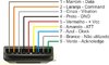
first off did you sand down the edges after trimming I see a lot crap on the edges, also provide a picture of the controller you are using.I added an image of the control area on the board I would like to know which pin of the green and gray wire on the board Model GH-061-51
CarlosC
.
- Joined
- Dec 12, 2021
- Messages
- 24
- Likes
- 1
the board is working normally i just need to know where to solder the gray and green wire of the ps2 controllerfirst off did you sand down the edges after trimming I see a lot crap on the edges, also provide a picture of the controller you are using.
Attachments
I mean a picture of the controller pcb being used, then you could easily do a continuity check between the wires that are soldered on motherboard with wires soldered on controller.the board is working normally i just need to know where to solder the gray and green wire of the ps2 controller
CarlosC
.
- Joined
- Dec 12, 2021
- Messages
- 24
- Likes
- 1
I think you didn't understand I just want to know where I solder the 2 loose wires my board is different from the one here on the siteI mean a picture of the controller pcb being used, then you could easily do a continuity check between the wires that are soldered on motherboard with wires soldered on controller.
I do understand I’m trying to help you the way I can. Simply use these pins to trace them back to the solder points then use the picture you provided to check what pin is what start from left to right with first pin being ackI think you didn't understand I just want to know where I solder the 2 loose wires my board is different from the one here on the site
- Joined
- Apr 6, 2020
- Messages
- 129
- Likes
- 355
You don't need to solder the gray wire, it's just for the vibration motors.the board is working normally i just need to know where to solder the gray and green wire of the ps2 controller
- Joined
- Apr 6, 2020
- Messages
- 129
- Likes
- 355
PCB finish is not good, remove cut chips and file edges of PCB. Another thing, I don't know what your intention is in the project, but for a portable Ps2 you don't need to solder the controller and memorycard 2.I do understand I’m trying to help you the way I can. Simply use these pins to trace them back to the solder points then use the picture you provided to check what pin is what start from left to right with first pin being ackView attachment 21294
- Joined
- Apr 6, 2020
- Messages
- 129
- Likes
- 355
Green wire goes to the first controller pad on the board.ok but still have the green wire
Bro he can’t find the solder point on motherboard for green wireGreen wire goes to the first controller pad on the board.
hello guys,i'm new here and have a few questions,how do i power the ps2 using battery,what voltage suitable and are there wiring diagram for powering ps2 using battery?
Your question should be in its own thread not hijacking another as it's not related, but as per Gunnar on discord you were pointed to the trim guide for this information, Here. There's more in the guide hub on the forum for how to figure out the rest
Similar threads
- Replies
- 18
- Views
- 7K
- Replies
- 5
- Views
- 4K