
- Joined
- Jan 28, 2016
- Messages
- 60
- Likes
- 661
The Definitive PS2 Trimming Guide
Preface
Preface
This guide focuses only on the 7900X series motherboard as it is the smallest PS2 motherboard with its integration of the custom ASIC. The guide will feature two trims at different skill levels that both remove essential components for the operation of the disc drive. Therefore, a Free McBoot memory card and a USB drive will be used to load games using Open PS2 Loader.
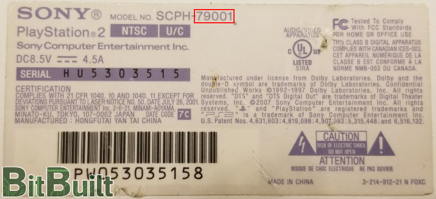
A 7900X series motherboard can be found inside a PS2 Slim model and identified from the label underneath the console enclosure.
Trimming
You should have a clear understanding of this guide before you begin trimming. It is recommended to remove the ethernet port before trimming the motherboard. The large ICs, resistors, capacitors, and connectors that the trimming lines go through are perfectly safe to cut through and remove. It is important to fully remove these components and clean the pads if needed so there are no shorts on the board. The 7900X motherboard is a 4 layered board so it is crucial that you sand the edges of the motherboard with at least 600 grit sandpaper after cutting.
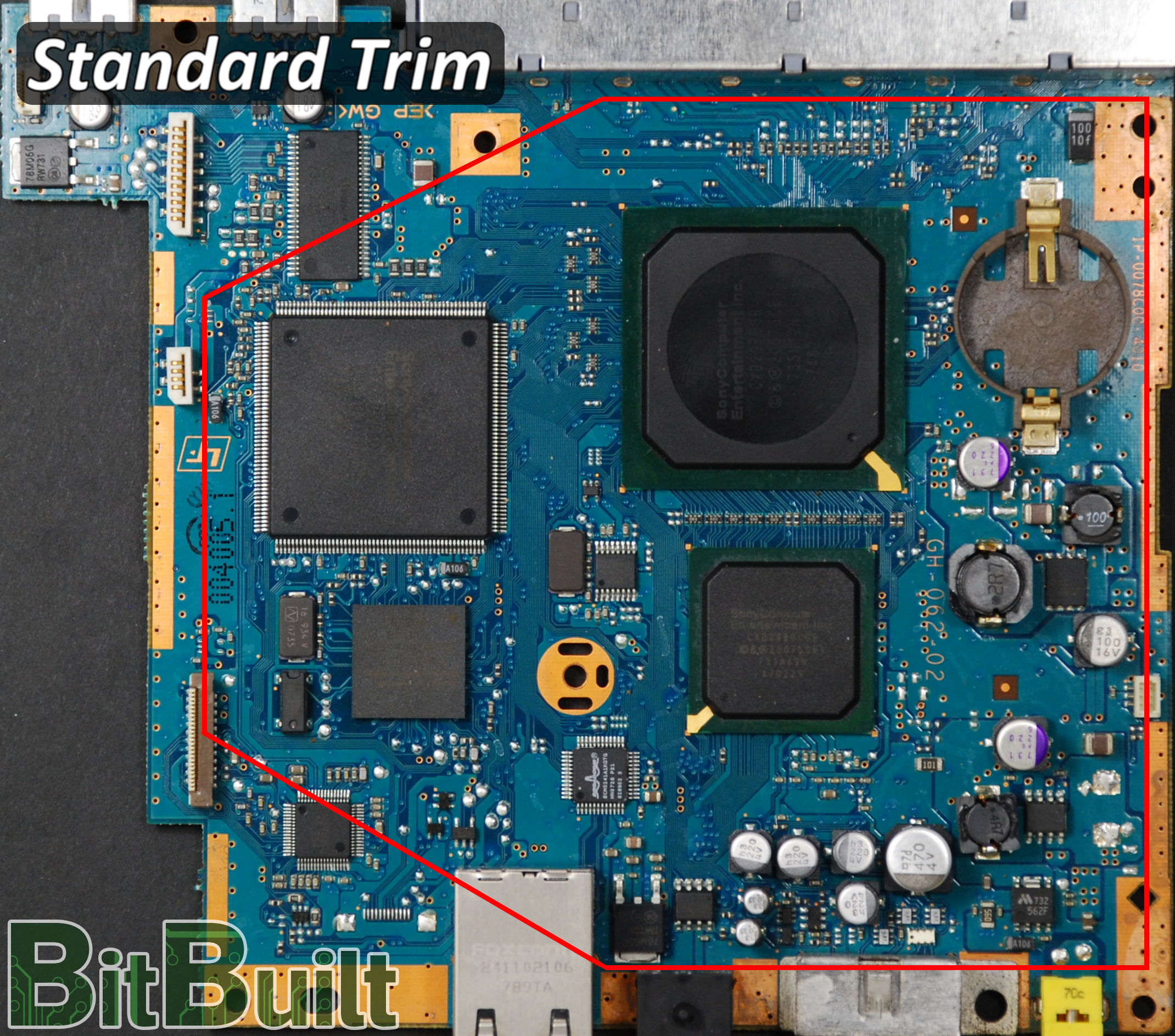
The Standard Trim
The Standard Trim is the simplest trim for beginners to accomplish because it has only two requirements to boot. It must have:
- Standard voltage relocation
- Reset button

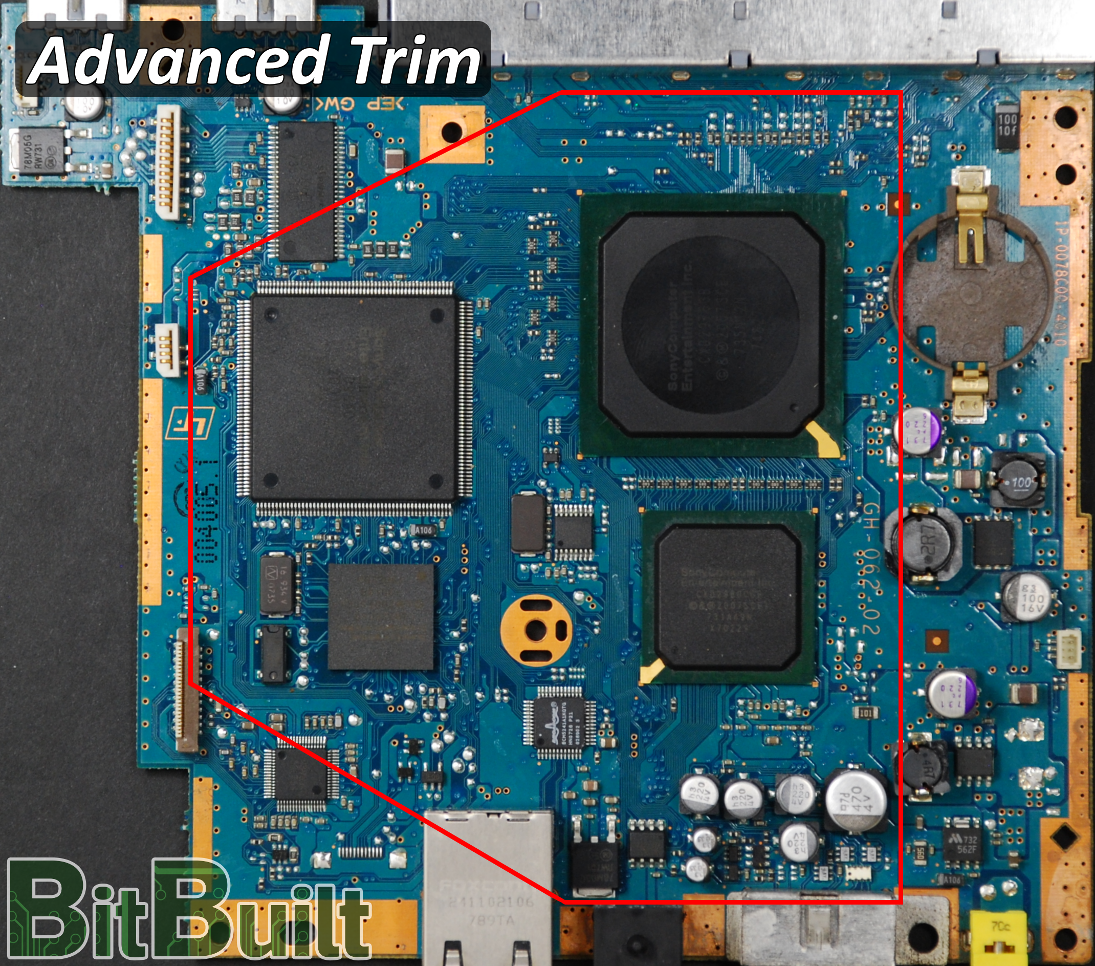
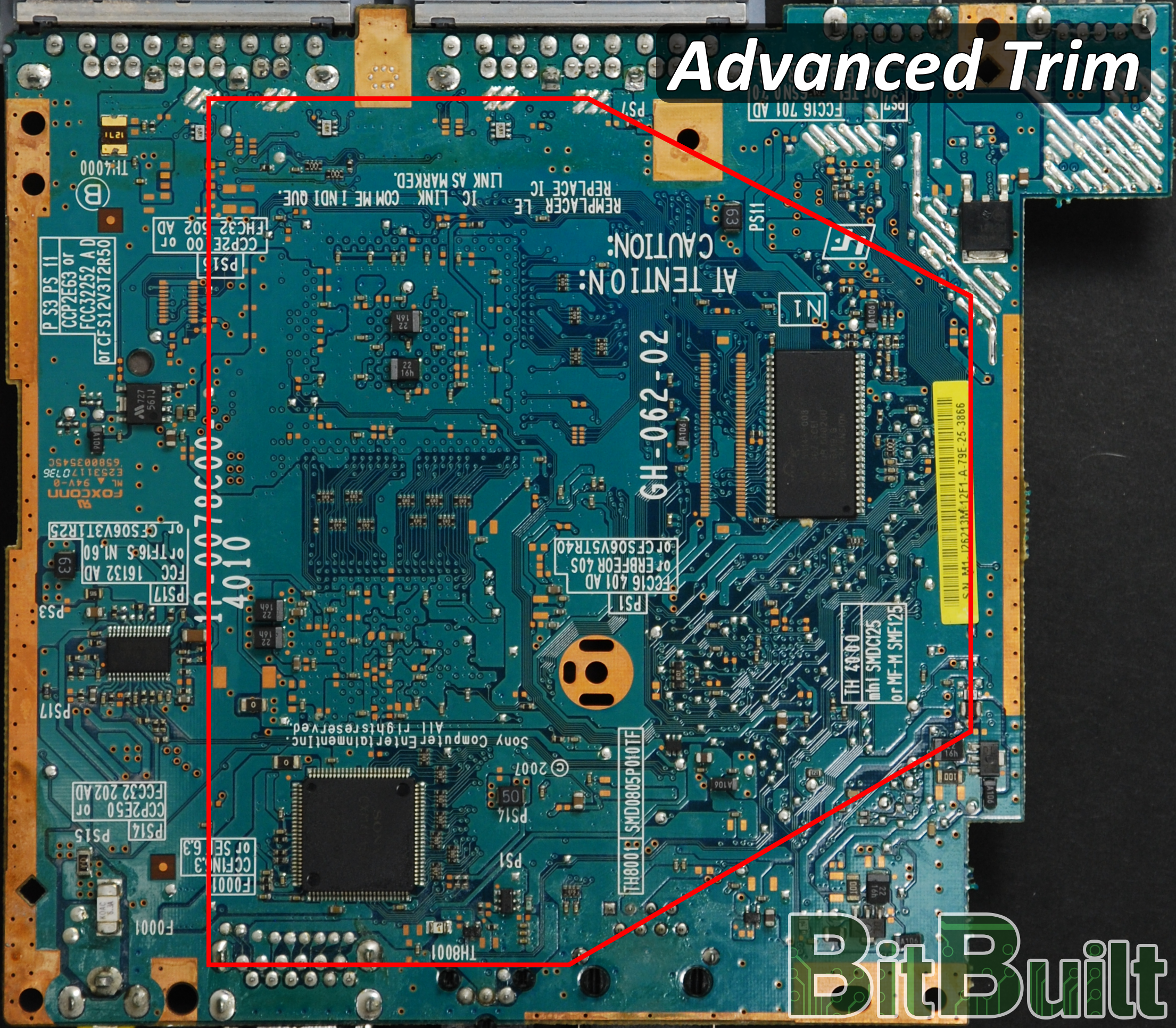
The Advanced Trim
The Advanced Trim also has two requirements to boot. It must have:
- Advanced voltage relocation
- Reset button
Standard Voltage Relocation
Voltage relocation for Standard Trim:
- 8.5v (can be powered from a 7.4v battery pack)
- Wire 5v to the 8-pin audio dac
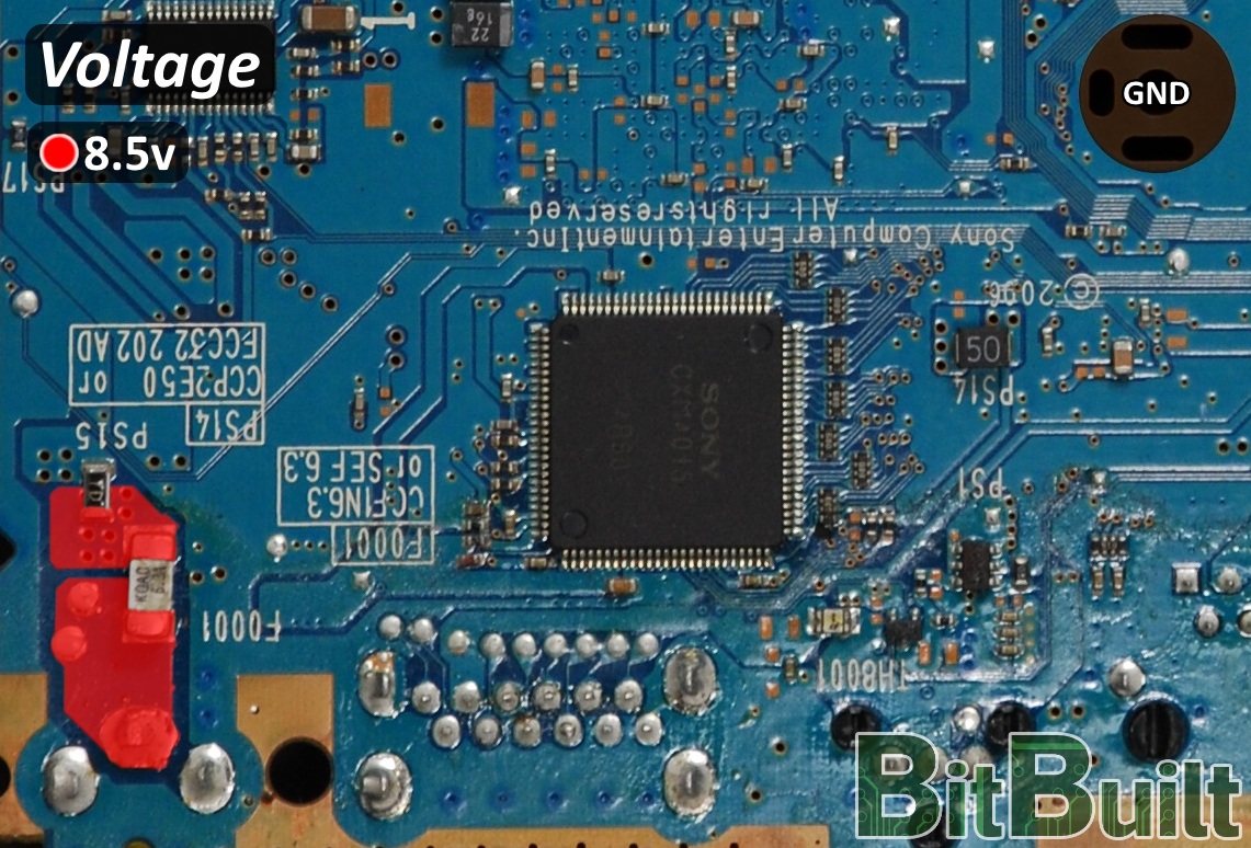
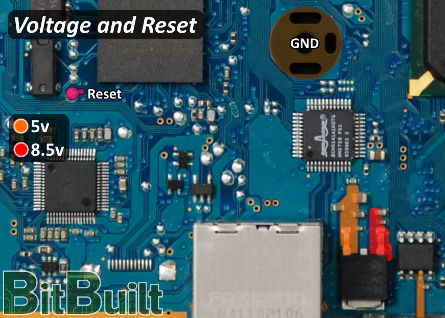
- The reset button is used to turn the PS2 on and operates as a normally-open tactile switch shorting to ground
- 8.5v must be relocated to both the power plug and the 5v linear regulator
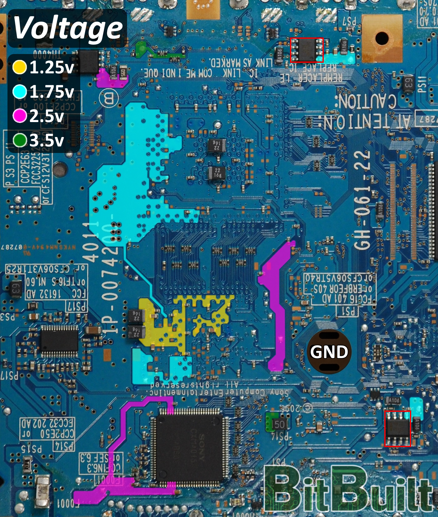
Advanced Voltage Relocation
The Advanced voltage relocation replaces the on-board voltage regulator circuitry with custom regulators. While more difficult, it provides a few advantages:
- Opportunity to lower the overall power consumption of the PS2 by using more efficient regulators
- Ability to trim the board smaller
- Custom regulators (1.25v, 1.75v, 2.5v, and 3.5v)
- All voltage points labeled in the diagram must receive the specified voltage
1.25v ~3.1A
1.75v ~0.1A
2.5v ~0.1A
3.5v ~0.1A
Notes:
- The 1.25v regulator will source 3.1A. Choose a regulator that is capable of providing enough current.
- The PS2 may be unstable if the 1.75v regulator is a switching regulator. It is recommended to use a 1.75v linear regulator so there is less noise on the voltage output.
79001 and alike:
79003 and alike:
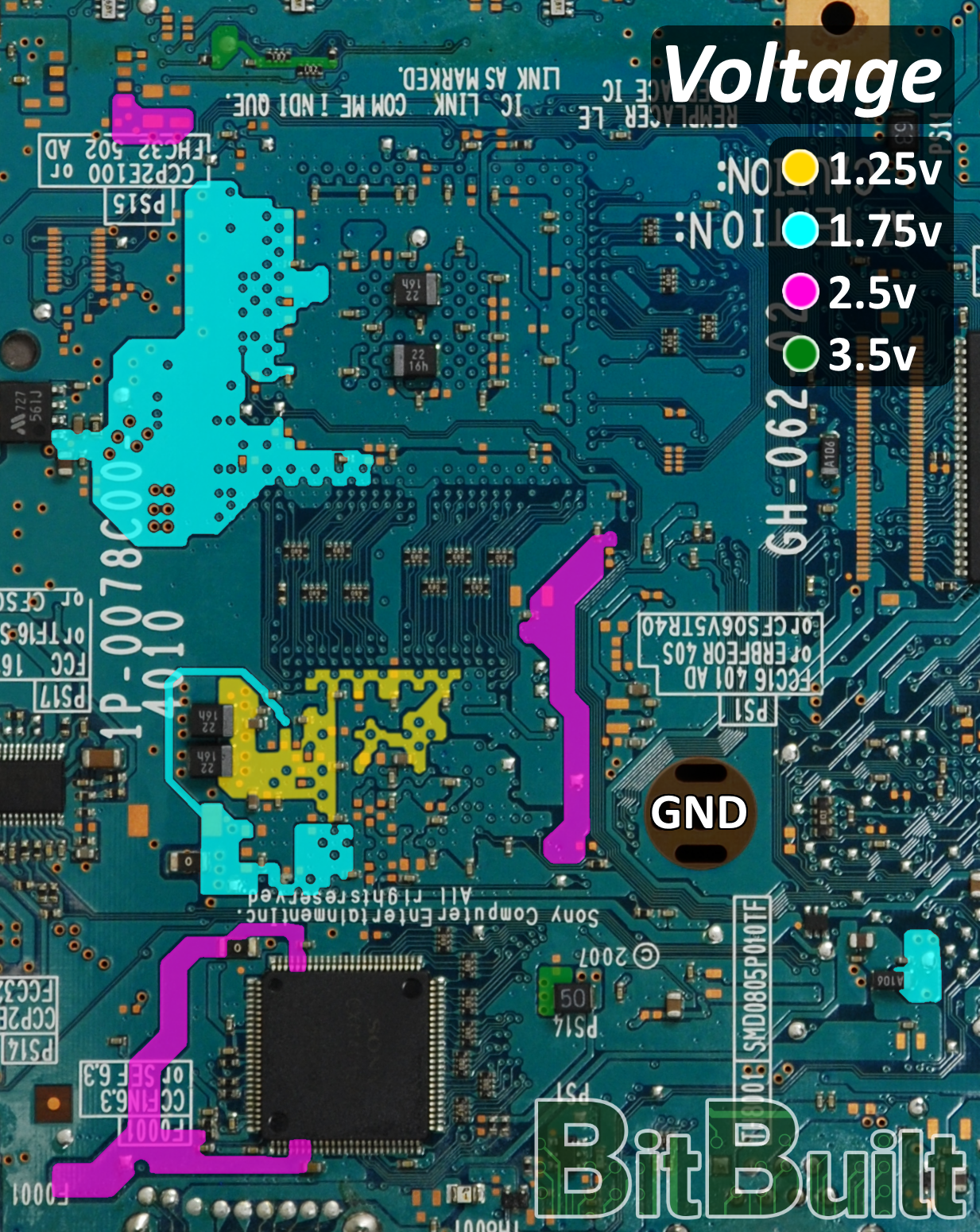
- When using custom regulators and the 8.5v relocation is not wired, there will be one more 3.5v relocation point on the 8-pin IC.
Audio/Video
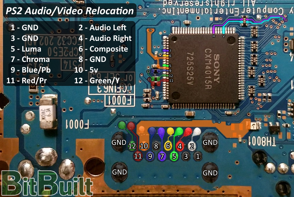
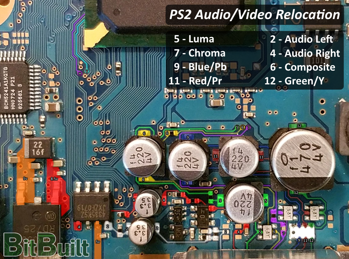
- The CPU outputs a 1.7v logic level Horizontal and Vertical sync so native VGA can be easily achieved using the sync signals and RGB; no need for a YPbPr-to-VGA converter. However, most PS2 games do not support progressive video so your screen should be compatible with an interlaced signal.
PS2 Controllers
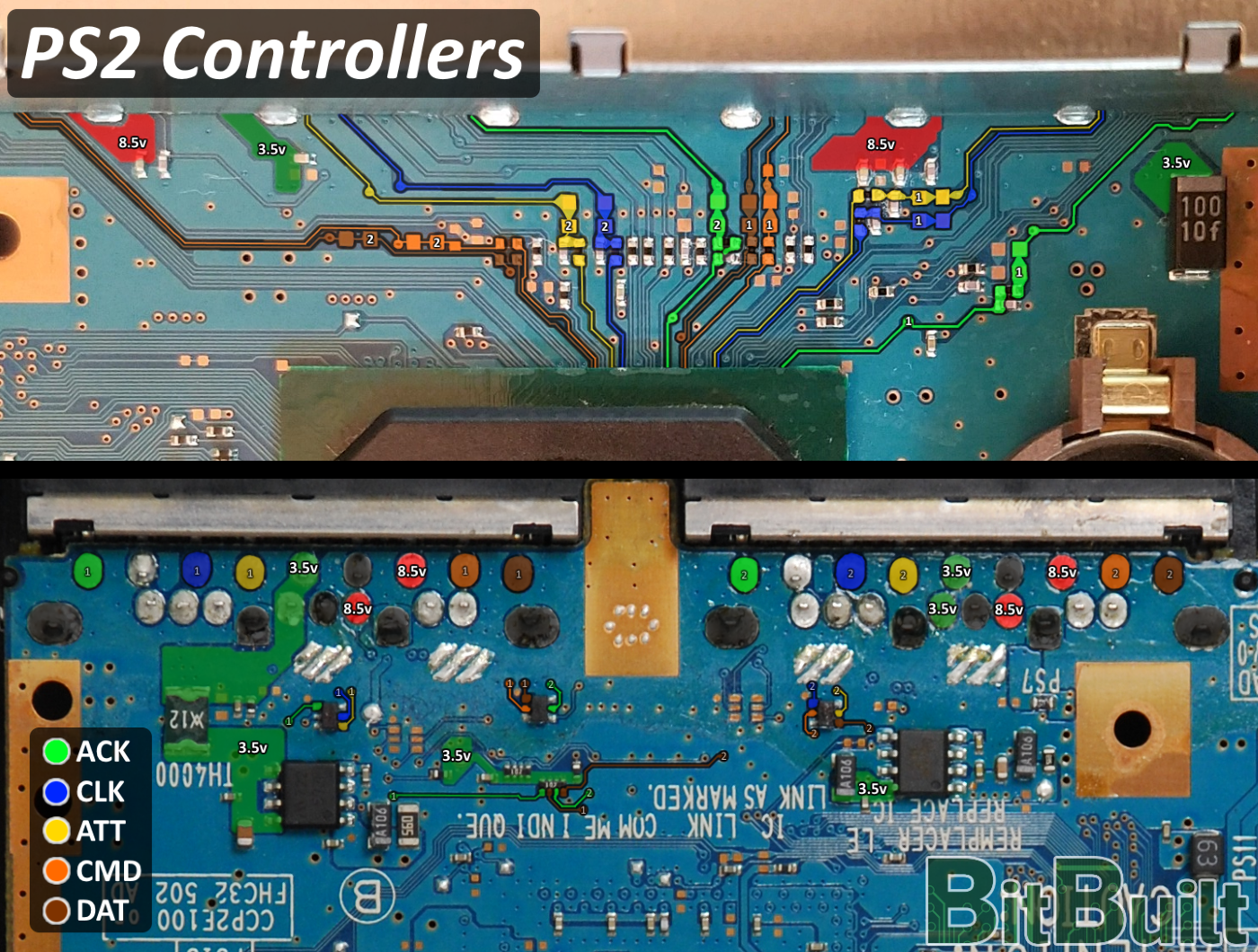
- 8.5v is only required for controller rumble.
PS2 Memory Cards
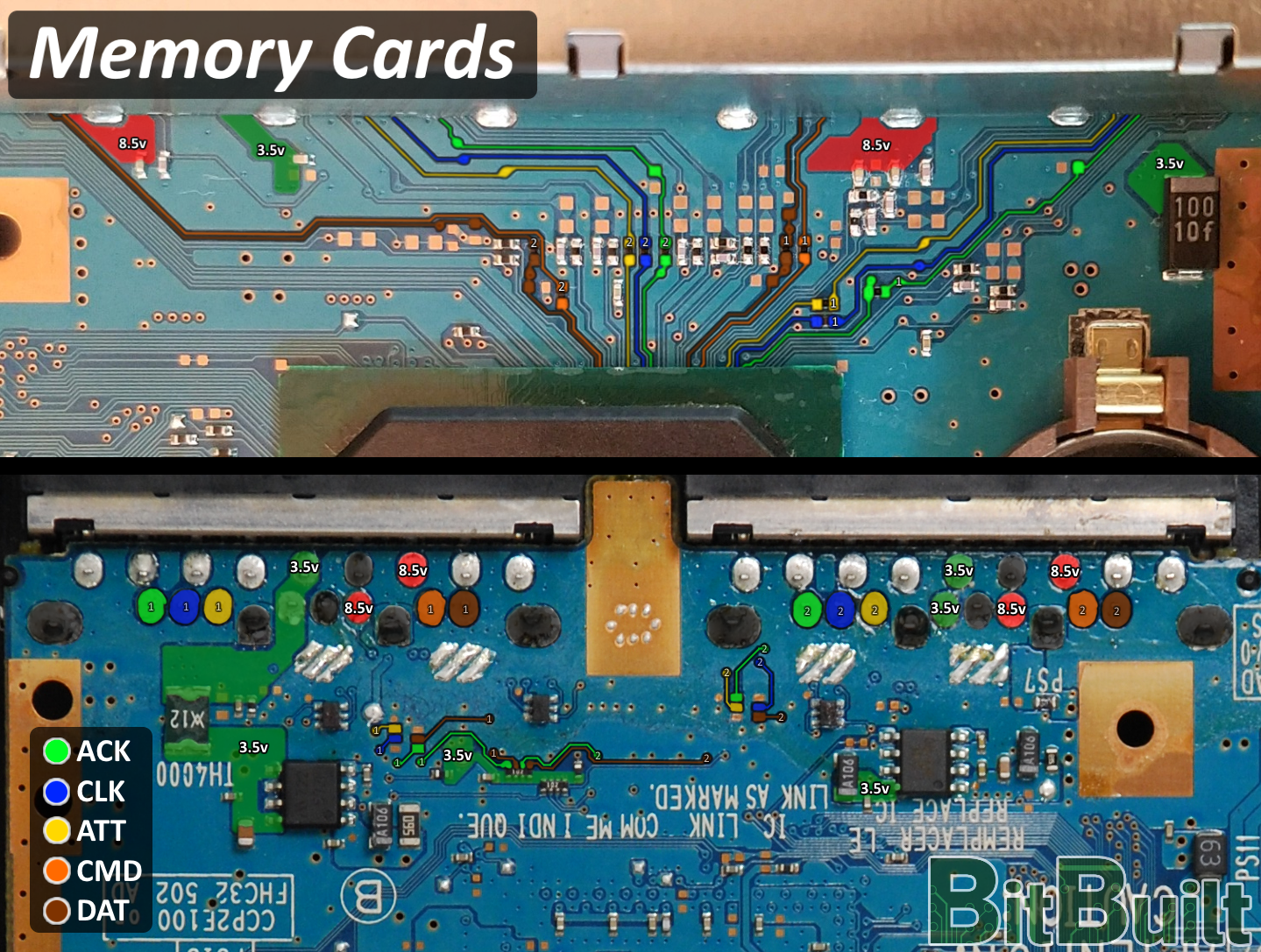
- A Free McBoot memory card is recommended to be relocated on Slot 2. Open PS2 Loader features a Virtual Memory Card compatible with most games so a memory card on Slot 1 is optional.
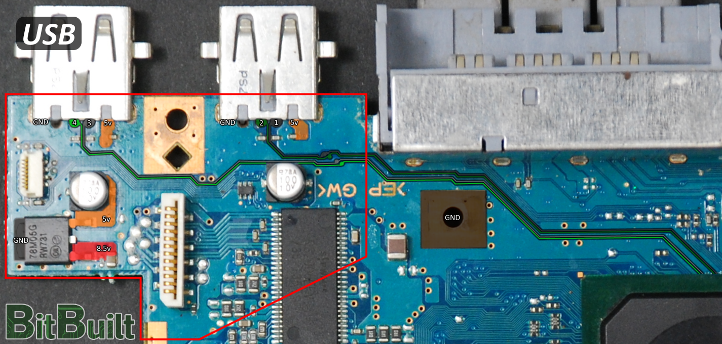
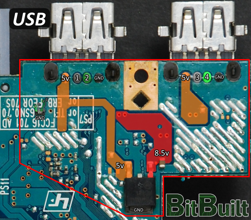
USB
USB is one method for loading homebrew on the PS2. Relocation of the USB data lines will require you to scratch the solder mask off the pcb and solder to the trace. This can be done using 38 AWG magnet wire. A pull-down resistor (15k ohm resistor) must be connected from each USB data line to ground.
It may be beneficial in some circumstances to simply trim the corner of the board off like shown. This way you can retain the USB ports, pull-down resistors, and 5v regulators. Don’t forget to sand the edges of this board as well.
CMOS battery
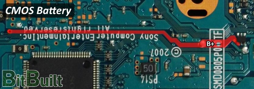
- The CR2032 CMOS battery is responsible for saving the time and date settings in the PS2. If this feature is not desired, it is not required to be relocated.
Postface
Feel free to ask any questions you may have about PS2 trimming and thanks for reading!
Credits
Gman - established the compendium, tested everything and accomplished the first PS2 trims, and created all images used in this guide
Lightning - provided the sanded PS2 motherboard for the compendium
Aurelio - general electronics expertise
Shank - provided photographs of the motherboards used in the diagrams
Changelog
10-08-19- Added voltage diagram for full custom regulators. -Gman
Last edited by a moderator: