Worklog Indigo G-Wii rev 2 Revived

Alvaro

.
Joined
Nov 29, 2016
Messages
94
Likes
40
Location
somewhere
Portables
2
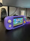
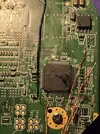
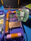
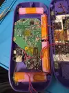
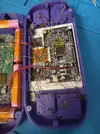
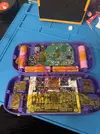
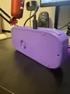
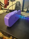
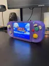
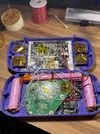
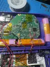
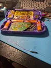
Basically 6 years ago I built a G-Wii with sub par skills and tools. It stopped working pretty fast and I never got around to fixing it. Years later my soldering skills and tools have gotten much better. I finished the G-Wii in about 3 days from scratch (Including desoldering, disassembly and cleaning some very stubborn flux residues from fake ebay flux that aged badly).

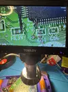
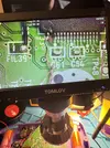
Some mishaps happened while fixing the board up which i had to figure out. My HS/VS pins had no more pads and I accidentally broke VS pin off while probing to troubleshoot VGA. I basically just winged it and grinded back the AVE chip a bit and soldered a wire there lol. Then it turned out the VGA was not working because the VGA patches weren’t applied so I went to wire up the GC+ just to navigate RVLoader in composite and run the installer and then it thankfully worked great! Also had to resolder the wire to the 3.3v on the nand. In the end here are the pics just so I can document some stuff I suppose. (Last pic is from when i finished it 6 years ago to compare)

Also on a side note, I hooked up the U-Amp to SCW and SDW but also wanted the physical buttons to work with the HUD. I can’t find any info despite hours of searching and the one video mentioning it by Aurelio was made private. So does anyone know which GPIO pins I should hook my + and - volume buttons to?

The only one I found info of was the HS pin which I also have wired to the U Amp.

Anyways thanks for all the hard work and information thats out there already!
 

Attachments

  • IMG_5895.webp
    IMG_5895.webp
    282.3 KB · Views: 2
  • IMG_5866.webp
    IMG_5866.webp
    488.1 KB · Views: 3
  • IMG_5867.webp
    IMG_5867.webp
    642.5 KB · Views: 3
  • IMG_5865.webp
    IMG_5865.webp
    783.5 KB · Views: 2
  • IMG_5839.webp
    IMG_5839.webp
    1.9 MB · Views: 3
  • IMG_5856.webp
    IMG_5856.webp
    807.5 KB · Views: 2
  • IMG_5879.webp
    IMG_5879.webp
    578.2 KB · Views: 3
  • IMG_5880.webp
    IMG_5880.webp
    637.4 KB · Views: 3
  • IMG_5882.webp
    IMG_5882.webp
    951 KB · Views: 2
  • IMG_5887.webp
    IMG_5887.webp
    272.3 KB · Views: 2
  • IMG_5886.webp
    IMG_5886.webp
    266.3 KB · Views: 2
  • IMG_5896.webp
    IMG_5896.webp
    568.4 KB · Views: 2
  • IMG_2690.webp
    IMG_2690.webp
    1,016.5 KB · Views: 2
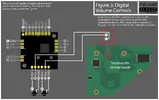
Alright well I was browsing around 4layer and stumbled across the RVL-AMP. In those diagrams I found the GPIO via for digital volume controls. I could not find this anywhere else! And I have a U-AMP so I was always just looking at those pinouts instead. A little crazy no amount of googling or searching could find that info because its on a picture diagram lol… Anyways, I want to enable digital volume controls with my U-AMP. I was told I can hook up to the GPIO pins and bridge all jumper pads but that’s it. Upon reading the diagram it says to hook up the button to the RVL AMP first then AMP to GPIO via because it requires a 3.3v pull up resistor for it to work.

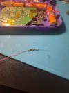
So what did I do? I attempted to implement my own pull up resistors because I don’t think the U AMP has any. I did this and it’s not working. I’m a bit of a noob at the technical knowledge but I believe I implemented this right and it’s just not functioning. Some help would be greatly appreciated because this has been driving me crazy lol.

I wired 2 10k resistors to 3v3 directly then from there two wires on the end of each. From those wires one goes to the button and the other goes to the GPIO via. After researching and looking at diagrams, this should technically work right? The junction is at the end of the resistor where it should be pulling GPIO pin high when the button is not pressed and then when the button wire shorts to ground it’ll pull this low and suppose to send command. Input would be greatly appreciated thank you!
 

Attachments

  • IMG_5926.webp
    IMG_5926.webp
    911.2 KB · Views: 2
  • IMG_5925.webp
    IMG_5925.webp
    1 MB · Views: 2
  • IMG_5923.webp
    IMG_5923.webp
    530.4 KB · Views: 2
  • IMG_5921.webp
    IMG_5921.webp
    640.4 KB · Views: 2
  • IMG_5927.webp
    IMG_5927.webp
    234.2 KB · Views: 1
Last edited:
I'm still wondering if anyone has any idea about this. Been waiting on closing my Gwii up again because of this. If I can't achieve it I must undo the digital volume control stuff and put my old configuration back. Here is a diagram of my wiring if it'll help anyone understand what I have currently.
volume.webp
 
The diagram says that the RVLAmp has pull up resistors on it already. Also, I would personally recommend having Wii HUD disabled. WiiHUD is already enabled for the battery life percentage in games, and there's really no need to have a volume bar visualizer. Some games have visual artifacting problems due to WiiHUD, and the volume wheel only exaggerates them from my experience. You can just have all the jumpers on the U-Amp closed and you'll get audio without the HUD.

Also the diagram you're seeing that says the wires for this need to go to the Wii motherboard are only for Wii HUD control. This is for if you want to adjust the volume up and down with Z, Y, and the Dpad. There's no need for this on builds like the G-Wii since it has it's own dedicated volume buttons, and it's limited to only working in games/apps that support Wii HUD which doesn't include a lot of homebrew apps. So you end up without volume control in those cases annoyingly. Just another reason why I recommend don't recommend Wii HUD unless you need it like on the G-Boy.

That indigo color is beautiful btw!
 
Last edited:
I'm not really sure where you're getting the need for pullup resistors to be added to this circuit. If pull up resistors are necessary, they're almost certainly already on the U-Amp. All you really need is the tact switches going between the volume buttons and ground.

Also, I would personally recommend having Wii HUD disabled. WiiHUD is already enabled for the battery life percentage in games, and there's really no need to have a volume bar visualizer. Some games have visual artifacting problems due to WiiHUD, and the volume wheel only exaggerates them from my experience. You can just have all the jumpers on the U-Amp closed and you'll get audio without the HUD.

Also the diagram you're seeing that says the wires for this need to go to the Wii motherboard are only for Wii HUD control. This is for if you want to adjust the volume up and down with Z, Y, and the Dpad. There's no need for this on builds like the G-Wii since it has it's own dedicated volume buttons, and it's limited to only working in games/apps that support Wii HUD which doesn't include a lot of homebrew apps. So you end up without volume control in those cases annoyingly. Just another reason why I recommend don't recommend Wii HUD unless you need it like on the G-Boy.

That indigo color is beautiful btw!
Indigo is indeed a very nice color! Also, yes this is my point exactly, I wanted to have the onscreen HUD with the physical buttons (I already have SCW and SDW connected so the controller button combo works). I don’t really use homebrew so it working in games only is fine by me. Aurelio had told me it was possible on the U-AMP but that is all the info I got so I decided to try after finding the diagram.
IMG_5927.webp

This diagram is meant for the RVL-AMP which does support WiiHUD digital controls with physical buttons. It has two Vol+ and Vol- pads because as stated in the top right it has a 3.3v 10k pull up resistor for the wii GPIO to function. Now the U-AMP does not have such pads or information so I assume it does not have the 3.3v 10k pull up that I need. This is all new stuff to new me so after researching what this all meant I decided to try and implement it myself, however it does not work.
 
  • Like
Reactions: cy
I apologize, I misinterpreted the information on your original post here.

I'm a bit confused here still, doesn't the U-Amp documentation have everything you need for it to work? If so, why are you looking at the RVLAmp? It looks like it works a bit differently on the U-Amp than it does on the RVLAmp. I'm pretty sure the SCL and SDA lines on the U-Amp are needed for the Wii HUD. I know the amp works if you just hook up C, D, MC, and WS. And since the PMS2 taps into the Wii using SCL and SDA, it stands to reason that the U-Amp is doing the same. So if you just have the jumpers and the SDL and SDA lines connected, I'm pretty sure you'll have all you need.
 
I apologize, I misinterpreted the information on your original post here.

I'm a bit confused here still, doesn't the U-Amp documentation have everything you need for it to work? If so, why are you looking at the RVLAmp? It looks like it works a bit differently on the U-Amp than it does on the RVLAmp. I'm pretty sure the SCL and SDA lines on the U-Amp are needed for the Wii HUD. I know the amp works if you just hook up C, D, MC, and WS. And since the PMS2 taps into the Wii using SCL and SDA, it stands to reason that the U-Amp is doing the same. So if you just have the jumpers and the SDL and SDA lines connected, I'm pretty sure you'll have all you need.
This is also the problem! The U-AMP documentation never mentions GPIO for volume up or down and in fact that’s why I couldn’t find any information about it to begin with because I was only looking at the U-AMP. I stumbled upon the other diagram after just browsing around. The U-AMP also doesn’t sport two of each V+ and V- assuming because there is no 3.3v 10k pull up built in and the volume is simply activated by shorting to ground (but this has no hud like i wanted). That’s why I’m using the pull up resistors how I showed in the diagram I made. Completely skipping over the V- and V+ of the U-AMP and wiring directly to the GPIO pins with the pull up should theoretically activate Wii HUD on button press (i have the i2c hooked up like i mentioned). Alas I’m a noob and it’s not working.

Of course if I can’t get this working I will just go back to the non wii hud volume buttons. Everything else is working all I’m trying to do is use Wii HUD with physical buttons on U-AMP.
 
At this point, it honestly sounds like this is either an oversight, or there's something in the documentation that you're missing. Could genuinely be either, and it may be worth contacting @Gman about this. I would help more if I could, but I've never used Wii HUD before outside of the G-Boy which used older versions of these boards.

Sorry I couldn't be of more help.
 
Update: decided to do some poking around. Something I noticed was the GPIO wires measure almost 0v when the console is on which is weird because they should be being pulled up. I am thinking this may be my issue but I am unsure why. The voltage before the resistors measures 3.3v like it's suppose to. I've checked that my buttons are not shorting to ground.

Some more interesting things I found was the GPIO pins have 220ohm resistance to ground when the Wii is on and when its off it goes up to 500-700ohm for both the wire on and off the GPIO. Next I also found out that apparently it is the GPIO vias that are the reason the voltage is being brought down. I unsoldered them and amazingly the wires going to GPIO are reading 3.3v but only when not connected... so that means that the GPIO is always reading LOW when its connected which I would suspect is the reason the volume commands are not functioning. Someones insight would be great.

edit: I know the docs state that its uses a 10k pull up but maybe I could use something much lower?
 
Last edited:
Update again! I decided to contact Gman to just ask him directly and it turns out I was doing everything right lol... All I had to do was change the RVLoader volume control system setting to buttons instead of GC controller. To be honest I feel like I went through all the settings before and never saw that. Maybe I looked through it before I shorted the jumpers. Headache for naught but resolved in the end :) Thanks @Gman

The portable will now be closed up forever and I can play Wind Waker again :)
 
  • Like
Reactions: cy
Update again! I decided to contact Gman to just ask him directly and it turns out I was doing everything right lol... All I had to do was change the RVLoader volume control system setting to buttons instead of GC controller. To be honest I feel like I went through all the settings before and never saw that. Maybe I looked through it before I shorted the jumpers. Headache for naught but resolved in the end :) Thanks @Gman

The portable will now be closed up forever and I can play Wind Waker again :)
Nice dude! Were you able to fix the RGB LED battery life thing? I also didn't know there was a setting in RVLoader for that. Must have been added quietly lol. Glad you figured it out though!
 
Back
Top