

Basically 6 years ago I built a G-Wii with sub par skills and tools. It stopped working pretty fast and I never got around to fixing it. Years later my soldering skills and tools have gotten much better. I finished the G-Wii in about 3 days from scratch (Including desoldering, disassembly and cleaning some very stubborn flux residues from fake ebay flux that aged badly).
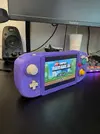
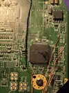
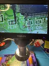
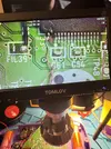
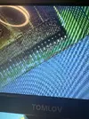
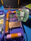
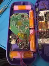
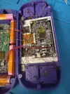
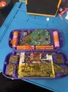
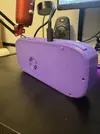
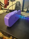
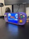
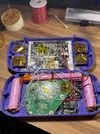
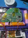
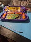
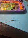
Some mishaps happened while fixing the board up which i had to figure out. My HS/VS pins had no more pads and I accidentally broke VS pin off while probing to troubleshoot VGA. I basically just winged it and grinded back the AVE chip a bit and soldered a wire there lol. Then it turned out the VGA was not working because the VGA patches weren’t applied so I went to wire up the GC+ just to navigate RVLoader in composite and run the installer and then it thankfully worked great! Also had to resolder the wire to the 3.3v on the nand. In the end here are the pics just so I can document some stuff I suppose. (Last pic is from when i finished it 6 years ago to compare)
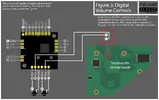
Also on a side note, I hooked up the U-Amp to SCW and SDW but also wanted the physical buttons to work with the HUD. I can’t find any info despite hours of searching and the one video mentioning it by Aurelio was made private. So does anyone know which GPIO pins I should hook my + and - volume buttons to?
The only one I found info of was the HS pin which I also have wired to the U Amp.
Anyways thanks for all the hard work and information thats out there already!
Some mishaps happened while fixing the board up which i had to figure out. My HS/VS pins had no more pads and I accidentally broke VS pin off while probing to troubleshoot VGA. I basically just winged it and grinded back the AVE chip a bit and soldered a wire there lol. Then it turned out the VGA was not working because the VGA patches weren’t applied so I went to wire up the GC+ just to navigate RVLoader in composite and run the installer and then it thankfully worked great! Also had to resolder the wire to the 3.3v on the nand. In the end here are the pics just so I can document some stuff I suppose. (Last pic is from when i finished it 6 years ago to compare)
Also on a side note, I hooked up the U-Amp to SCW and SDW but also wanted the physical buttons to work with the HUD. I can’t find any info despite hours of searching and the one video mentioning it by Aurelio was made private. So does anyone know which GPIO pins I should hook my + and - volume buttons to?
The only one I found info of was the HS pin which I also have wired to the U Amp.
Anyways thanks for all the hard work and information thats out there already!
Attachments
-
 IMG_5895.webp282.3 KB · Views: 8
 -
 IMG_5866.webp488.1 KB · Views: 6
 -
 IMG_5867.webp642.5 KB · Views: 8
 -
 IMG_5865.webp783.5 KB · Views: 8
 -
 IMG_5839.webp1.9 MB · Views: 6
 -
 IMG_5856.webp807.5 KB · Views: 10
 -
 IMG_5879.webp578.2 KB · Views: 11
 -
 IMG_5880.webp637.4 KB · Views: 8
 -
 IMG_5882.webp951 KB · Views: 7
 -
 IMG_5887.webp272.3 KB · Views: 7
 -
 IMG_5886.webp266.3 KB · Views: 8
 -
 IMG_5896.webp568.4 KB · Views: 6
 -
 IMG_2690.webp1,016.5 KB · Views: 6

 Thanks


