Gabobo
.
- Joined
- Jan 28, 2020
- Messages
- 62
- Likes
- 20
Sorry, I don't know how you guys would want me to do this on the forums but I'd like some expert thoughts on this. I also have some questions that I couldn't find answers for.
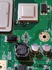
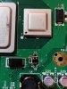
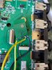
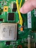
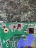
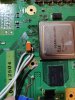
First, can anyone tell me if I removed the U10 and U9 correctly? The U10 has a bent corner leg and the U9's middle leg doesn't have that pop out like it's neighbor's.
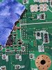
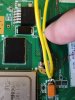
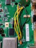
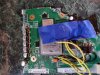
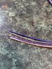
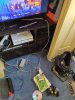
Second, some thoughts on the data wires. When are you supposed to braid the wires? I've seen work logs and videos of people doing that but I have no idea when I would want to do that. I was ready to do that all the time but that just feels wrong.
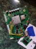
Third, people I know tell me to leave solder flux on but Google tells me it'll mess up my board. How should I clean off the flux? Obviously I've been told lies.
I'll try to ask questions sparingly so these are the only questions I have so far. Sorry if these have been answered already.
First, can anyone tell me if I removed the U10 and U9 correctly? The U10 has a bent corner leg and the U9's middle leg doesn't have that pop out like it's neighbor's.
Second, some thoughts on the data wires. When are you supposed to braid the wires? I've seen work logs and videos of people doing that but I have no idea when I would want to do that. I was ready to do that all the time but that just feels wrong.
Third, people I know tell me to leave solder flux on but Google tells me it'll mess up my board. How should I clean off the flux? Obviously I've been told lies.
I'll try to ask questions sparingly so these are the only questions I have so far. Sorry if these have been answered already.