[2025 Contest Entry] Summer Contest 2025-The WIIRTOP,a wii in a bartop(arcade cabinet)

If I make a kit, who will buy it?

  • Definetly me

    Votes: 6 85.7%
  • What is that thing again man?

    Votes: 2 28.6%
  • Nah bro,this thing sucks

    Votes: 0 0.0%

  • Total voters
    7
Joined
Jun 5, 2024
Messages
157
Likes
122
Location
a Lost Hole in France
Portables
1
Hello all!I'm happy to be here and to present my latest project,the WIIRTOP (the name could change during my worklog,it's not definitive).Like said in the title,it's actually a wii with an OMGWT trimm inside of a tiny little bartop,3d modelise by myself.
The idea comes when I was playing the best game ever, Sreet Fighter 2 and I was thinking,like"Hey,arcade cabinet are cool"and then I saw my wii and think"why not put a wii inside of this thing and do it portable?"and this project was born...
Unfortunaly,it was not the most original project of all times because I saw a few people on bitbuilt talking about doing something like this,but no finish products.
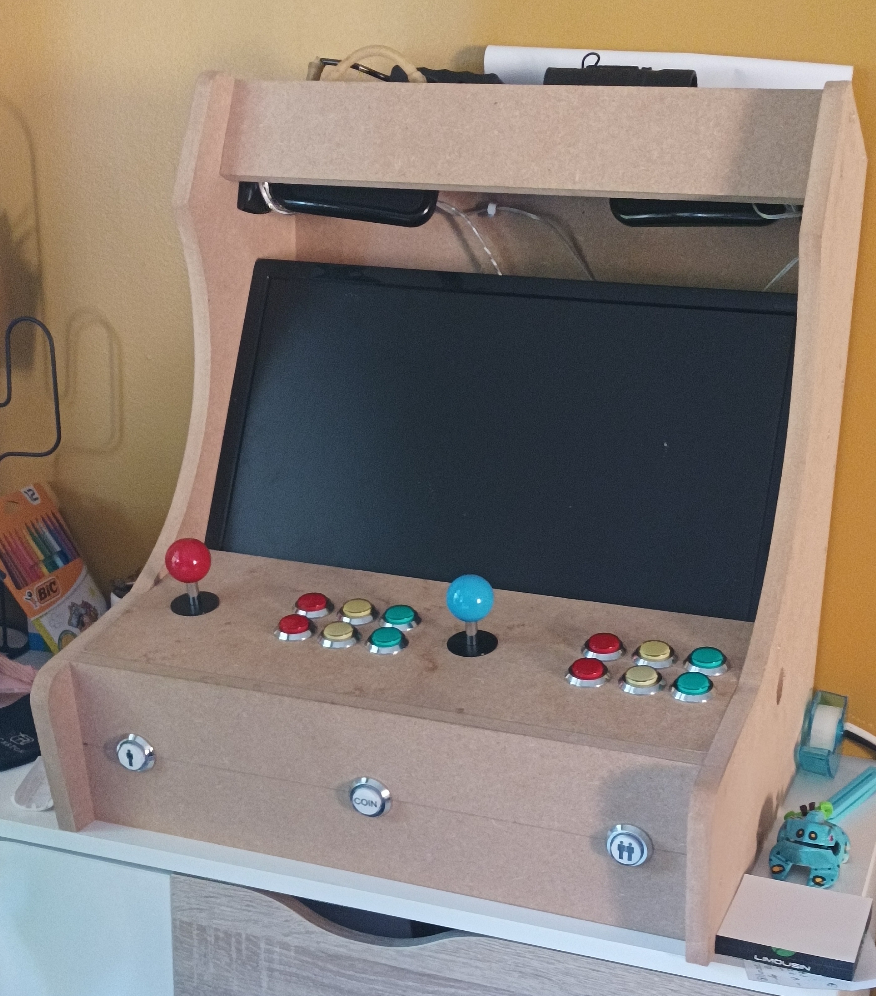
(Heres the arcade I done with my fatherB|,so cool I know)
1000040697.jpg

My base was this plan,which is the same plan I use for this thing
Capture-plan-BarTop.JPG

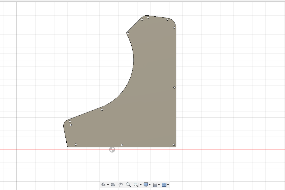
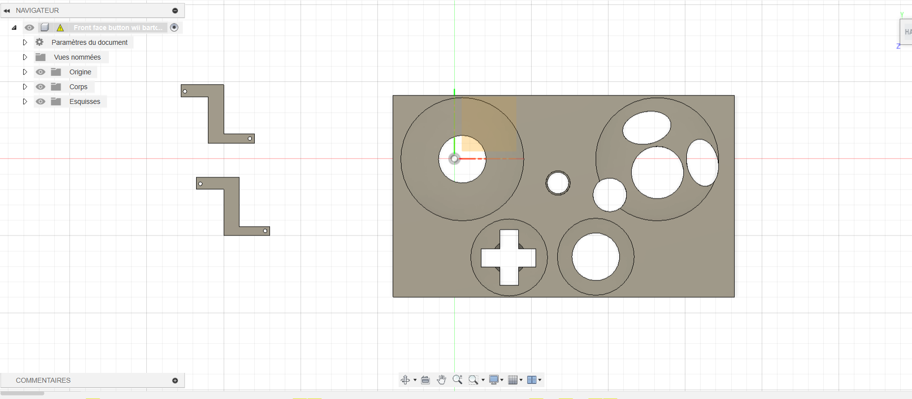
First,I create the controller panel and decide aproximately the dimensions of this thing,which was not too hard becasue I would like to use a 5 inch panel.
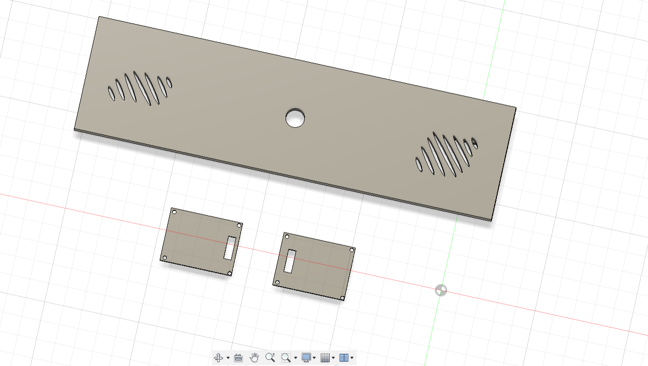
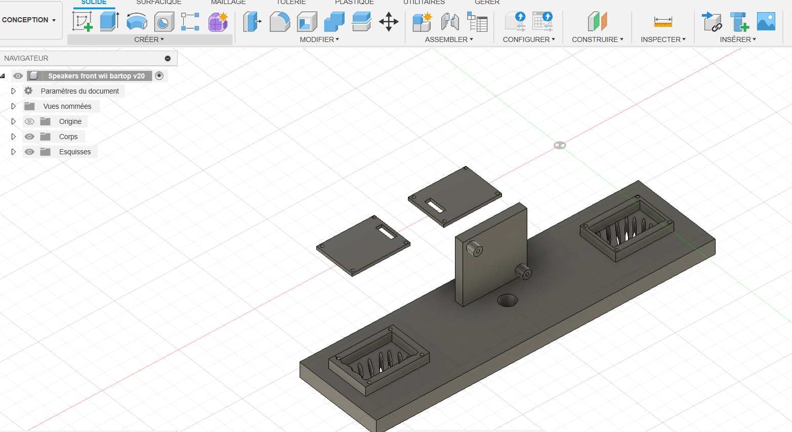
So,after hours of 3d modeling in fusion 360,I finally got a design I was happy with who also got screw points for help(because glue sucks).
Capture.PNG
Capture2.PNG
Capture3.PNG

Capture6.PNG
Capture7.PNG


The speakers(the weird thing at right)has been grandly inspired by the g-boy ones(and also by the Spotify logo as well,don't ask why,I don't know:XD:),it also use screw points for the Uamp2,but here is the thing:
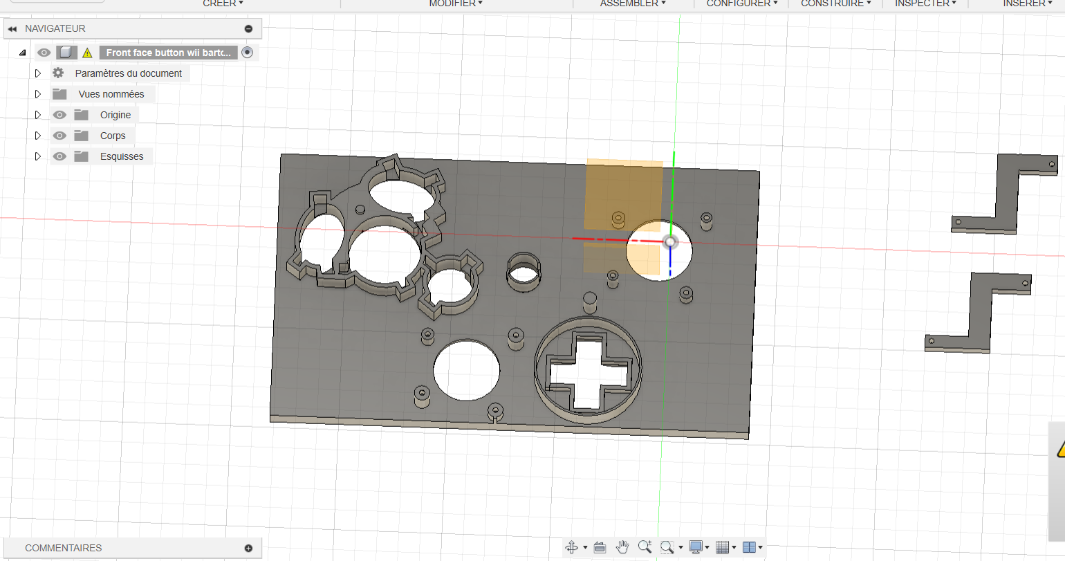
I don't have a 3d printer yet,so I can't done proper prototype,so that's why there are already screw points based on 3d model I found on Bitbuilt.

Thanks to @Luigid for his 3d modeling of his gamecube button on open-source,it helps a lot!

I already have a little idea of my internals,I think I will use 18650 cells,a rumble motor,GC ports,joycon joystick and more...

I was also doing my first steps in PCB design and creation.
Big thanks to @Xenii who gives me a lot of advices and take the time to help me at understand all this new domain<3.
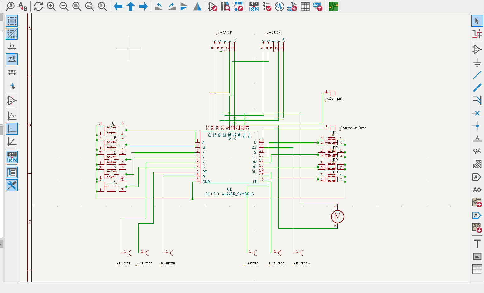
So,here is my controller pcb:
Capture4.PNG

(Sorry for the old modors of Bitbuilt which eyes can be fire due to the potential non-existent symbols which I create myself:blush:)

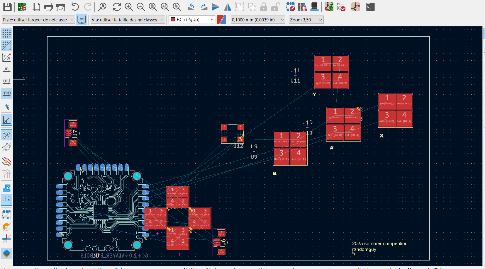
And after,the schematic,the best part,the pcb!(by the way,which is not finish yet)
Capture5.PNG

I will definitely do my works with 4layerTech module because it's a lot easier.
And that's all for this part.
Nothing to do with this worklog,but,for those who help me for my other worklog(a g-boy rev4u),especially @Stitches who help me a lot,just know that I will finish it(just waiting for some parts)because,when I began something,I need to finish it.
Hope see you next time:D!

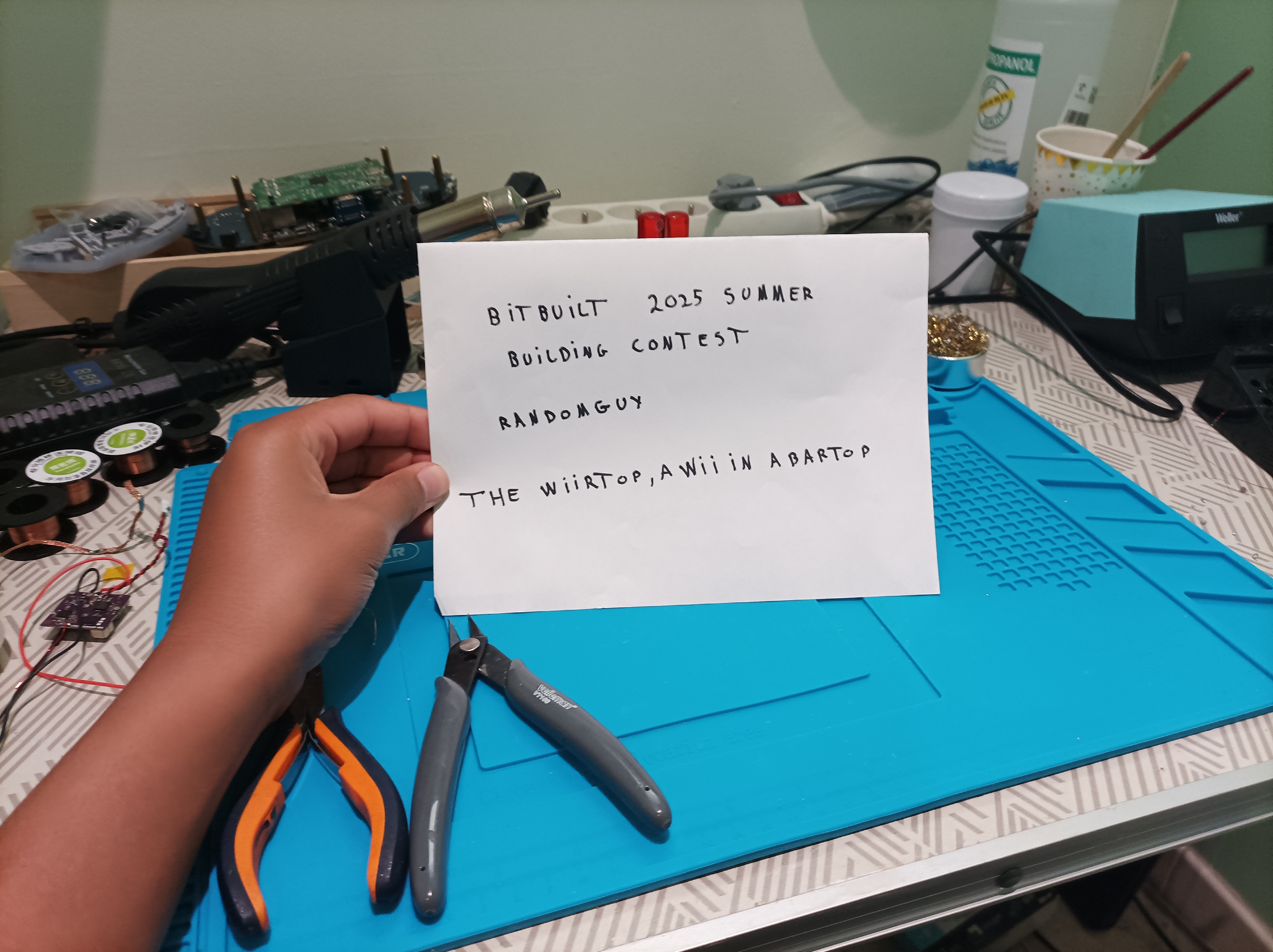
EDIT:Something important which I just forget
1000040761.jpg
 

Attachments

  • Capture3.PNG
    Capture3.PNG
    152.3 KB · Views: 123
Last edited:
Hello all!
Just got a small update and a 3d render of my console,but I didn't notice the screen was a little bit too small for my portable.Know,I hesitate to keep it like this or to modify it a lot for have something which will be more similar to the plan.Let me know what is the best option for you :)
Capture1.PNG
Capture2.PNG
 
Last edited:
Hello all!
Remember the weird render of this morning?Well,after some consultation with my brain,I finally decide to change it.So know,I got two updates in a day and a render who is much,much,much better than the old one who just give his place.
Here the new render(and I promise the next update will be something bigger)Also,for modify it,I use the best technic ever created,which is "take something and cut it in half".
Enjoy the result.
Capture3.PNG
Capture4.PNG
Capture5.PNG
 
Hey all!
Just finish the main controller pcb which looks a little messy,but that's my first pcb so I'm happy of it!
Here it is
Capture8.PNG

Capture10.PNG

Capture11.PNG

It will support rumble motor from WII remote and all the triggers of a normal Gamecube controller.Now,I just need to desgin them,but need to think about the design:rothink:(Get too much idea)
I also created a small led pcb for WS182 rgb led (the small ones) with super big pads for an easy soldering and another probably no-existant schematic which just take me 15 minutes.(Too easy for meB|).
Capture12.PNG

Capture13.PNG

Capture14.PNG

And I think that's all for today.
See you next time!;)
 
This is a really neat concept! I like the whole arcade cabinet aesthetic you're going for! Do you plan on having any art on the side walls of it? Might be kinda neat to see some Smash Bros Melee styled artwork on the sides of it.

Your PCBs don't look bad for a first go, but I would like to give some constructive feedback since I think there's room for improvement. The first thing I noticed is that you've got traces routed for ground which over-complicates the design effectively doubling the number of traces you need to run. Instead, I would suggest having a ground plane that connects all the grounds together. Another thing that I think could be improved upon is the trace routing. In 2 layer design, you want to route as much as you can on one layer while minimizing the number of traces you route on the other layer. You can add vias for the sake of redundancy and filling any major voids in the board that aren't connected to the ground pour. Finally, for the actual trace routing, I'd try to route the traces closer to each other only branching off when they need to seperate.

Following these practices will lead to cleaner, more-organized results. With all that said, I applaud you for taking the initiative of designing your own boards for this! I know that learning how to use the software and do what people tell you to in it is half the battle. I hope this feedback helps you to improve your designs in the future! I look forward to seeing how this project turns out!
 
Thank you for the advices,I will change it a little bit for got something much cleaner as you say.I was not planing to add some art,but it could be a great idea because I also realy like the stickers that you can put on the Bartop like these
Capture16.PNG

For the back,I wanted to put Gamecube controllers ports,but it could be better with some art.I will try to design something for another update.
Anyway,thank you for your help:D
 
Last edited:
  • Like
Reactions: cy
Hey all!
New update, with the great advices of @cy ,I finally done my GC ports pcb, which looks a lot cleaner than my GC+2 pcb(but I still like my design of course)
By the way,Huge thanks to @vikMKW for doing open source the dimensions
index.php

Capture15.PNG

Capture17.PNG

And my probably wtf schematic :awesome:
Capture18.PNG

I also added ports for wiimote rumble motors on the panels,whit that done,I will be able to play with maximum of sensations>:)
Capture19.PNG

For that,I needed to dissasemble my long time friend of Mario Kart Wii/Mario party/Mario Galaxy and others...for take some mesurements for the motor,
But,it was for science,so,I think it's ok.
My poor little friend after the dismounting
1000040889.jpg

And,lastly,I made the hole on the back of the system and just created some aproximate GC ports for help during the process
Capture20.PNG

Capture21.PNG

And that's all for this time,see you at the next update!:)
 
Last edited:
Your design philosophy has improved, but I'm still seeing quite a bit of room for improvement. The main thing I'll focus on here is adding a Ground plane since you still haven't done that. Doing so makes Ground redundant on your boards which is typically the best practice.

Here's an example of one of my boards without a Ground plane:
Exhibit A.png

It doesn't have any traces going to ground because I rely on having the ground plane there to connect them all together.

Now here's the same exact board with a ground plane:
Exhibit B.png

As you can see, instead of routing traces for every ground, I simply have ground everywhere a trace isn't already being routed. This is why the board looks different, there is now copper going everywhere except for between the traces.

To add a ground plane in KiCAD, click on the "Draw Filled Zones" button here:
Exhibit C.png

It will change your cursor, and you can then start drawing anywhere outside the board's edge cuts for your filled zone. In the following pictures, you'll see I drew mine way outside the edge cuts to ensure everything is contained within the filled zone.

When you click to draw the first point for the filled zone, it will prompt you with this window:
Exhibit D.png

You want to ensure F. Cu and B. Cu are selected. This is for the front and back copper layers. From there you're going to select your Ground Net, if needed you can search using the filter above the list. After selecting ground, you can click "OK".

From there, you can start drawing the rest of your ground plane as such. Since both of us are using simple ground planes, we can just go anywhere outside the edge cuts. So I make a box that covers the whole board:
Exhibit E.png


The shape is finished once you trace all around the board and end on the start point:
Exhibit F.png


When you want to fill the ground plane with copper, just press "B" on your keyboard, and it will update with the new ground plane. You will need to update the ground plane whenever you make any changes to your board.

Exhibit G.png


For this reason, some people like to add their ground plane last, but it really doesn't matter as long as you update your ground plane by hitting "B" once you're finished designing the board. I still recommend updating the ground plane every so often so you can better design around it.

With that said, the ground plane tends to get in the way, so you can toggle off visibility by hitting this button here:
Exhibit H.png

The red arrow points to the button that toggles on visibility, and the blue arrow points to the button that toggles off visibility.

Expect to have to add vias occasionally to keep the ground plane intact and constant around the board. In the community, we like to add a few extra vias all around different parts of our boards to keep Ground as redundant as possible, you can observe this in my design.

Hope this helps! Again, knowing how to use the software is half the battle!
 
Thanks you so much for your incredibly detailled answer!I now understand wath you was saying perfectly and I just done it on my GC ports,it's look better now.
Capture24.PNG

Capture25.PNG

Capture26.PNG

I also worker on a trigger system,.My first idea was to make something really similar to the GBA SP triggers,but,it was a little bit too hard and unuseful,so,after some thinking,I finally got another idea,which is a lot more easy.
Capture23.PNG

And here is the new version
Capture27.PNG

Capture28.PNG

See you next time :)
 
Last edited:
Thank you for the kind words,it motivate me much!
By the way,I've got a new adnacement on my shoulder pcb,I now finish it,here it is(and thank you again @cy for your really helpful advice for the ground :D )
Capture29.PNG

Capture30.PNG

And on the WIIRTOP(which is now the definitive name:awesome:)
Capture31.PNG

Capture32.PNG

I also change a little bit my triggers who now look like that:
Capture33.PNG

And I guess that's all for today,see you next time;)
 

Attachments

  • Capture3.PNG
    Capture3.PNG
    58.6 KB · Views: 120
Hey all,don't post since a long time because I'm (trying) to finish my g-boy (and it's exams month,you know).
Since the last time, I finally decide of the placement of the battery and the pms 2
Capture34.PNG

It looks a little weird,but,with that design,I'm able to put 4 18650 batteries.
After some work on the pms-pd,I notice it's not the best to put it like on the photo because it will need a suuuuuuuper long hole on my front panel(the panel of the speakers)so I will just put it on the speakers panel next time.
And that's all for today(not to much things I know):Pbut I finally decide of all the placements of my components,so that's a good thing(you will see on a future update)
See you next time!;)
 
Hey all !Too much time has passed since the last post so,here it is !
I finallly finish the shoulder buttons pcb who know got the start button on it
Capture35.PNG

and modify the 3d file
Capture.36PNG.PNG

I also finalize the pms pd port
Capture37.PNG

Capture38.PNG

And now I just need to finish a few things like the sensor bar pcb and the screen fixation.
I will test all of this on my new 3d printer(also my first,we all begin somewhere :awesome: ), an incredible prusa mk3,I'm too happy:D!
By the way,I hope I will finish this project for the end of the competition and during the creation of this,I've got an idea:
"Why not do a kit of this like the g-boy?",so I will try to do one if this project is finished,but here is the question:
If I do a kit,who will buy it?

Well that's all see you next time:)

EDIT: I done a 2.0 version of the front pcb for the buttons.(I still say thanks to @cy for his great advice about the routing of the pcb,it's so helpfull!It looks a little weird but if it works,that's ok:P
Capture39.PNG

Capture40.PNG
 
Last edited:
Hello all, new update is here !
I finally decide of the placement of the wii inside the portable,it looks a bit weird but it should work,so that's okay.With that design,the wii motherboard will be mount on a slab,refresh by two heatsink of 35x35x10 mm(the same as in the ashida).
Capture41.PNG

Capture42.PNG

I also decide of the fan:It will be a noctua fan of 40x40x10mm(Yeah I know I've got good tastes B| ).By the way, a huge thanks to @jefflongo for put the 3d model of the wii,the gamecube logo who helped for the fan ventilation and for a few others model.Check this if you need help with your project.Model - Jeff's Assortment of Various Models | BitBuilt - Giving Life to Old Consoles
Capture43.PNG

The back of the portable looks crazy now>:)

Capture44.PNG

I also modify the shoulder buttons pcb for the fan.With that modification,the fan sit properly in the case
Capture45.PNG

Capture46.PNG

And that's all for tonight,
yeah it's actually 1 a.m in my country and I'm sleepy,so see you next time!:)
 
Hey all,sorry for the super long silence,I was to the land of freedom(that's what they say all)
1000042290.webp

And I was also focusing on my g-boy(who still got problem)so,you know,don't have a lot of time for the WIIrtop,but it's over now and I'm in full go mode on this project,you will heard of me in the next weeks>:)
I also print the buttons art who looks great,but still need some modifications by the way:facepalm:
1000043304.webp

I'm also happy on how the back of the Wiirtop is,because it looks even crazy with the components onB|
Capture47.webp

Capture48.webp

I was trying to inplement the original sliders of the GC controller and delete the Shoulder buttons pcb like a morron:facepalm:,and I re-begin from scratch,but it looks good,so I'm happy with it:)
Capture49.webp

And I finally finish my main controller pcb,I did not done too much change but it will be better than the 2.0 version,so I'm now at the 2.1 version
Capture50.webp

And I guess that's all for today,see you next time;)
 
Last edited:
Hey all,time as passed since the last update,I finally finish my BOM at least
Screenshot_2025-09-14-08-50-44-130_com.google.android.apps.docs.editors.sheets.webp

It will cost a little less than 250€,so that's a good price and I'm happy with,but because I don't have enough money,it will be very hard top finish it for the deadlines.I will do my best but,I tell you know,dont be surpised if that's not finish in time:\.
See you next time and I can promise you will get all the parts 3d printed!;)

Edit:I also consider to open an online jackpot for this project,but I think it dont sounds very good for most of people
 
Hey all,small but important update :!:
I open a ko-fi account for anyone who want to support the project,so please,if you're rich,send me a lot of money!>:)Nah I'm joking,but if you want donate a little tip,you can do it now.Every dollar helps me a lot because the goal is high!
Thanks in advance to anyone who consider support this project more and have a good day:D
Here is the link:
ko-fi.com/randomguy1

Yeah the goal is 300€ because of the shipping costs
 
Hey again all,tiny update here,I know I promised to get all the 3d printed parts print for this update,but I encountered a big problem with my printer,so,some repair needs to be done on it,but,at least,I upgrade the shoulder pcb ;) !

Capture51.webp

Capture52.webp

Capture53.webp

I can now choose if I prefer to play with a controller or with the face button directly on the bartop(for the player one only)
1000043594.webp
And guess that's all for today,see you next time:)

 
Last edited:
Back
Top