
Context.
Is a DS Lite with the video mod, but I didn't want to lose the upper screen, so I needed to add the dual wifi mod and have 2 different firmwares.
Tools. -
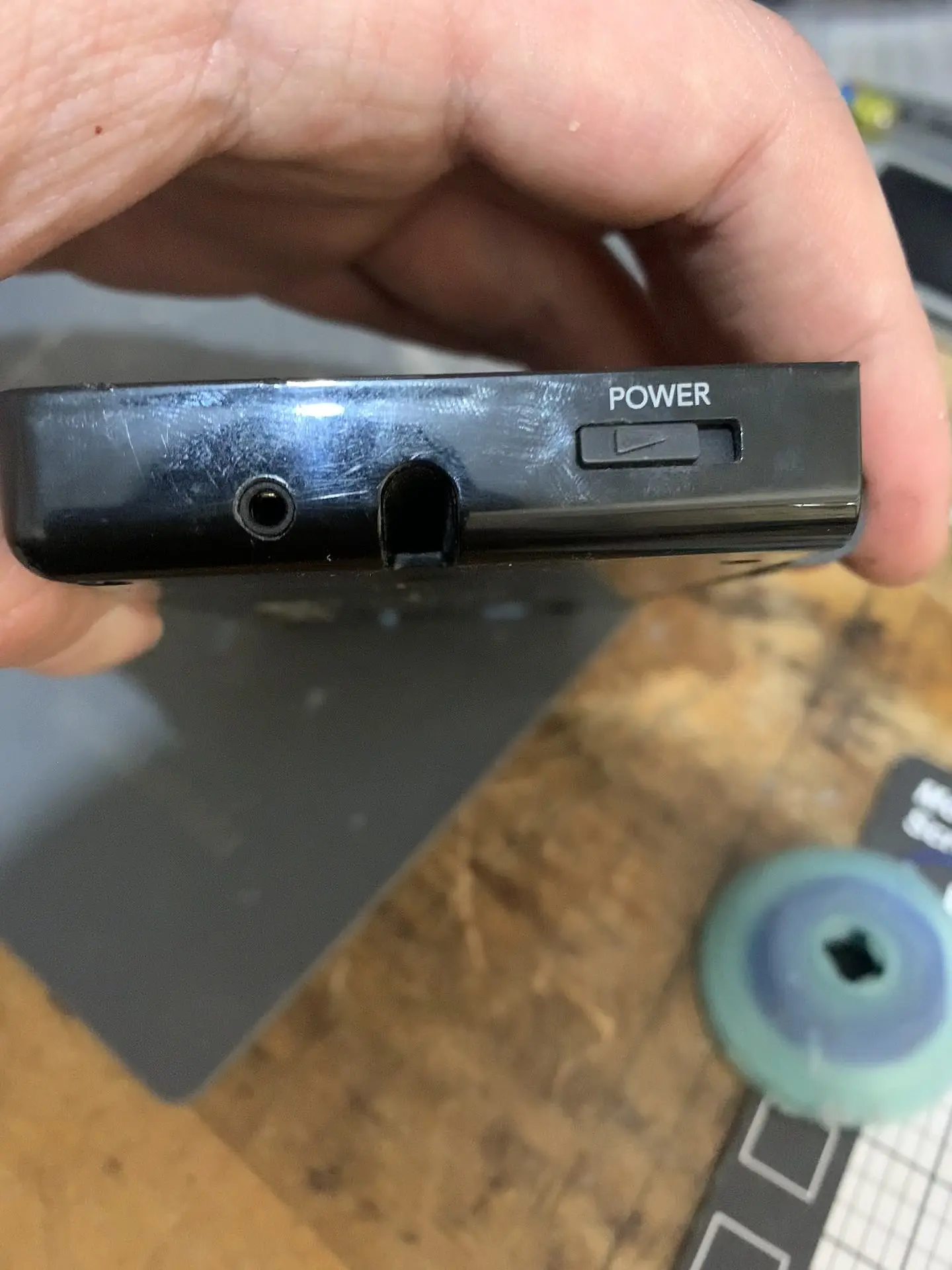
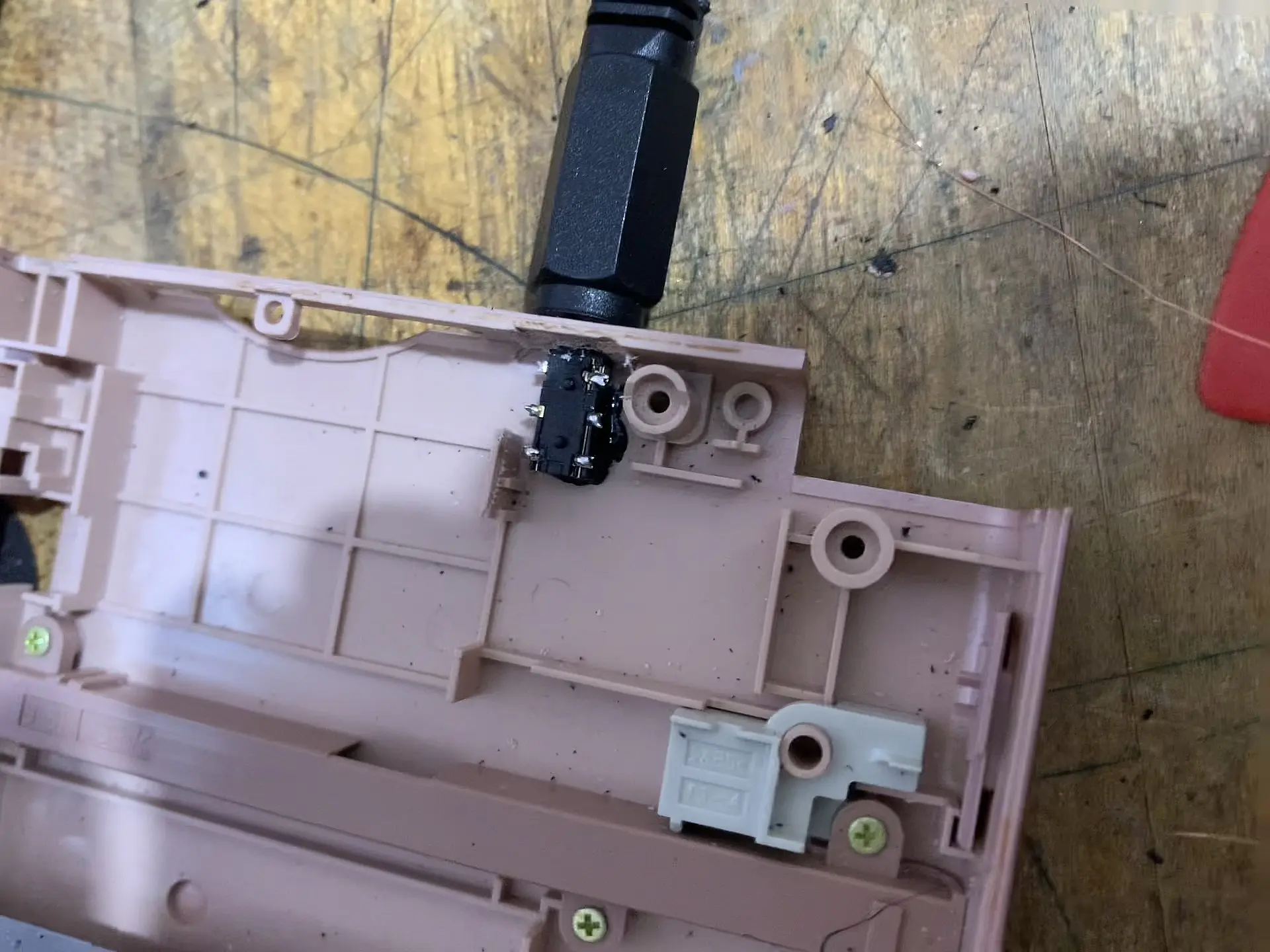
I liked how it looks on the side of the case, but I tough It was going to be uncomfortable to hold while playing so I decided to put it on the top.
I jumped the video wire to the 2.5mm connector then the GND signal to the motherboard then I soldered SPL0 and SPR0 to the connector (sorry I didn't have pictures of that)
basically, I jumped everything.
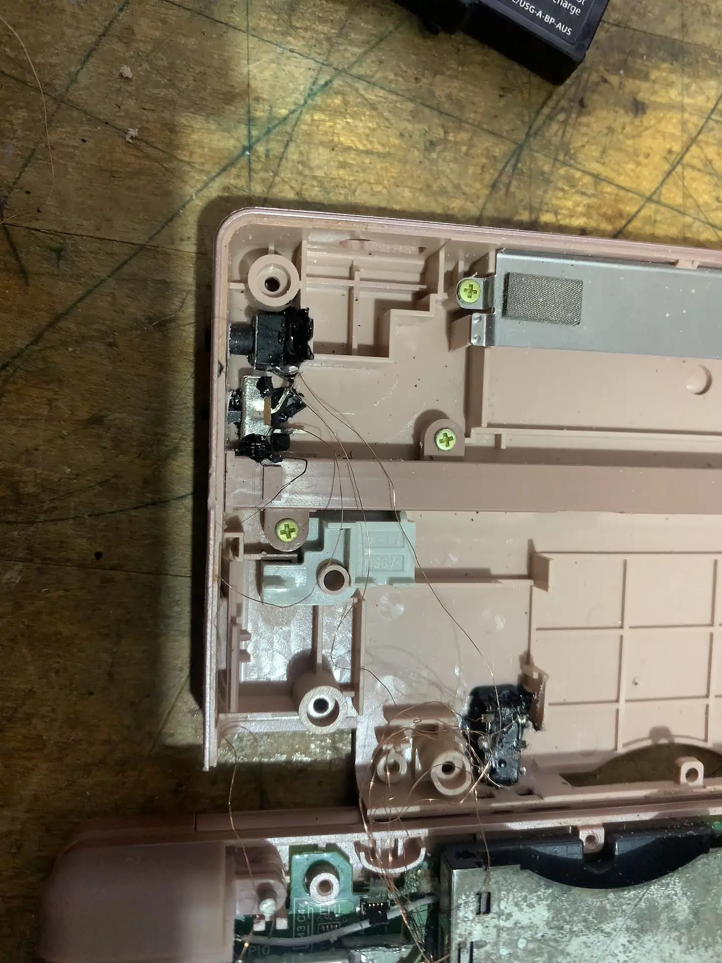
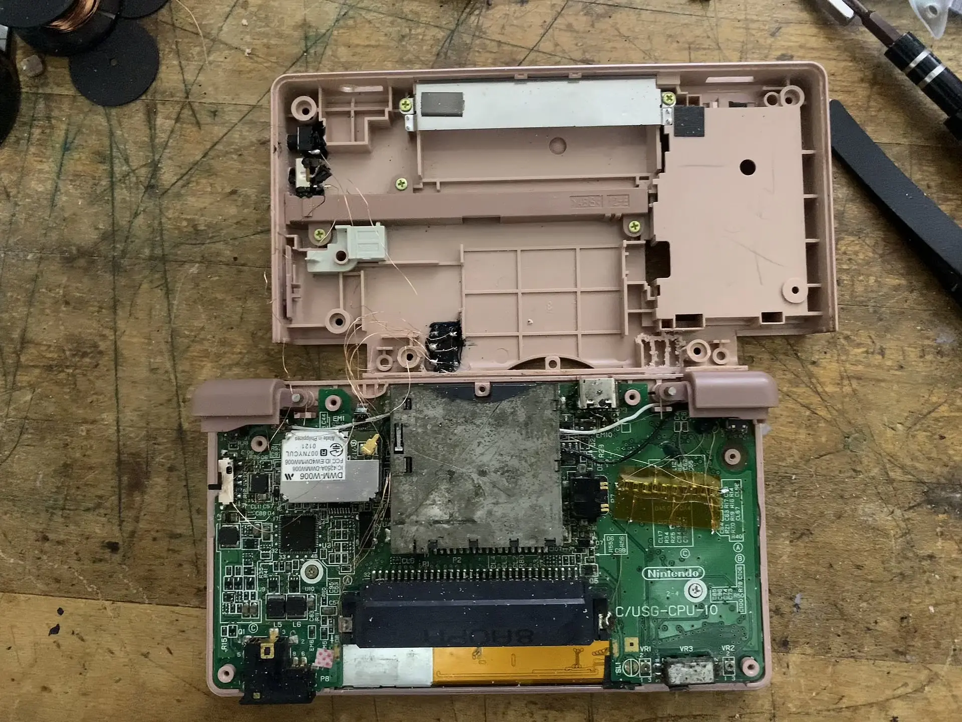
The switch's middle terminal is routed to GND also the pushbutton, I broke 1 terminal from the switch because I only needed to short the dual Wi-Fi to GND when I want to use the original firmware, if it is not shorted the ds boots with the video modded firmware.
The pushbutton is routed to P0 signal on the diagram.
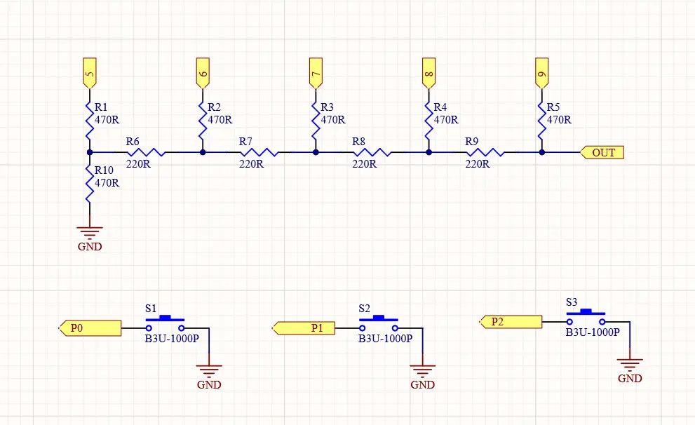
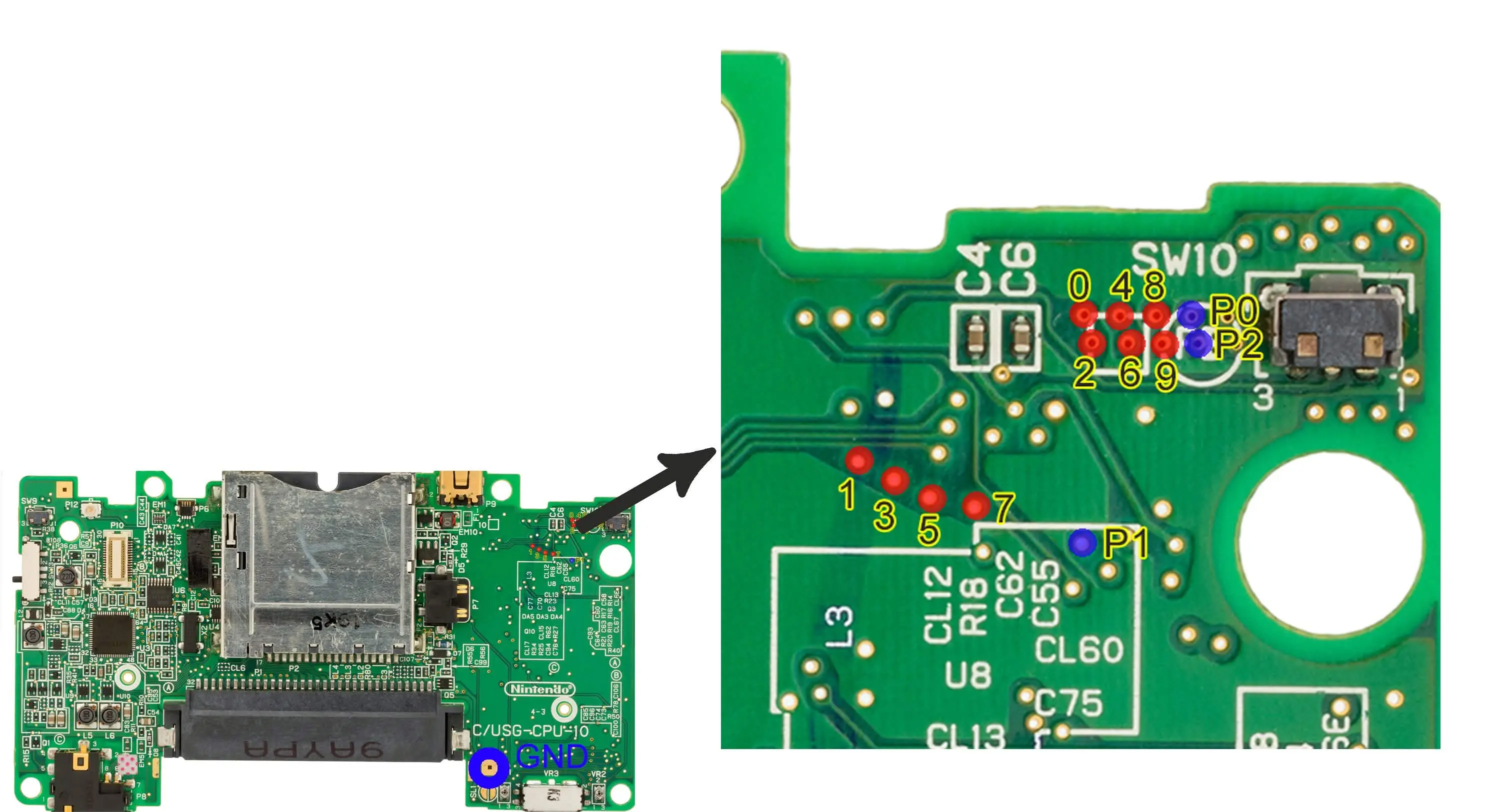
I only using the P0 signal button because I don't need the PiP or the transparency functions because I will be using only the screen switching while connected to a screen, when not I can use the two screens.
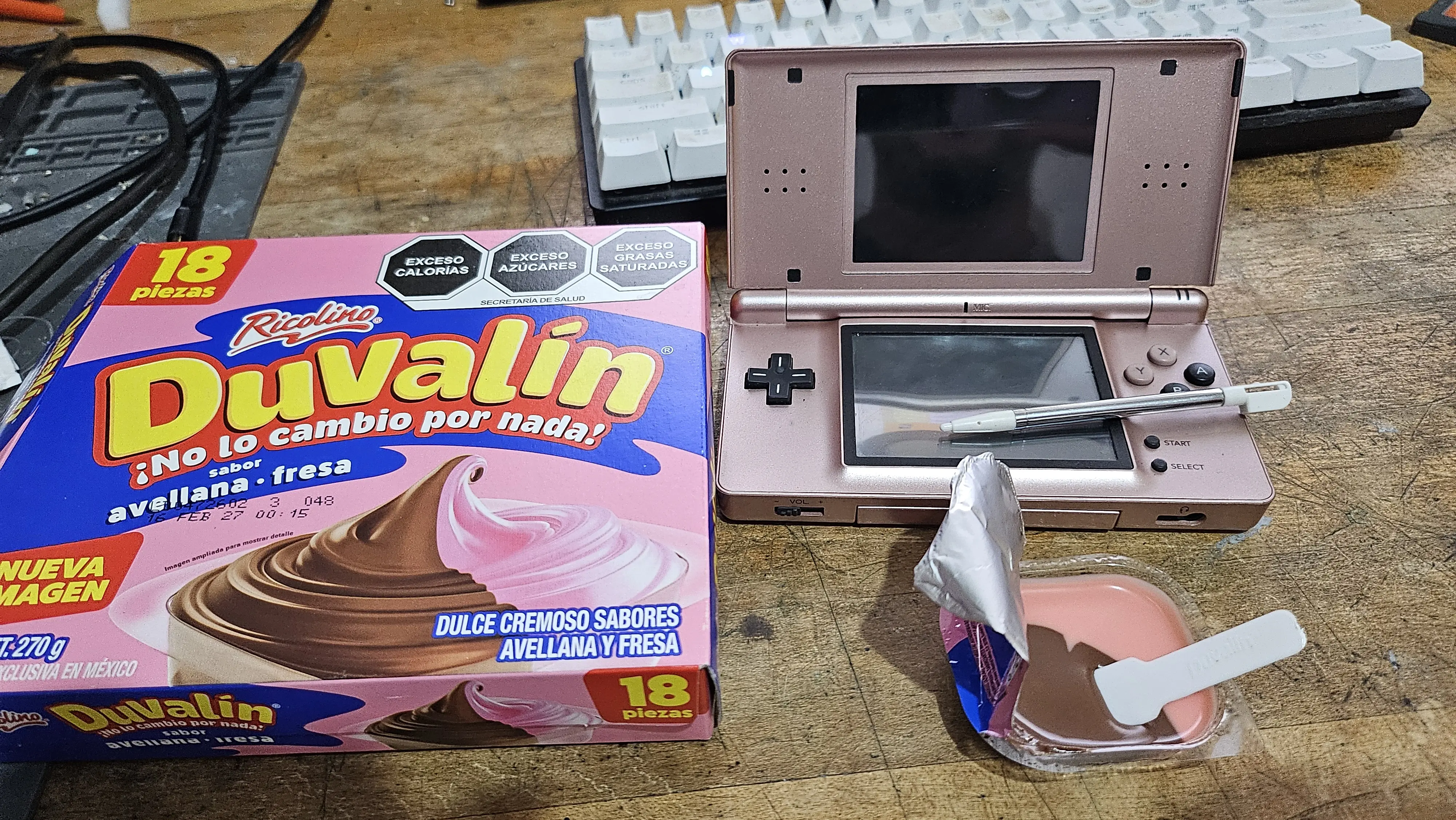
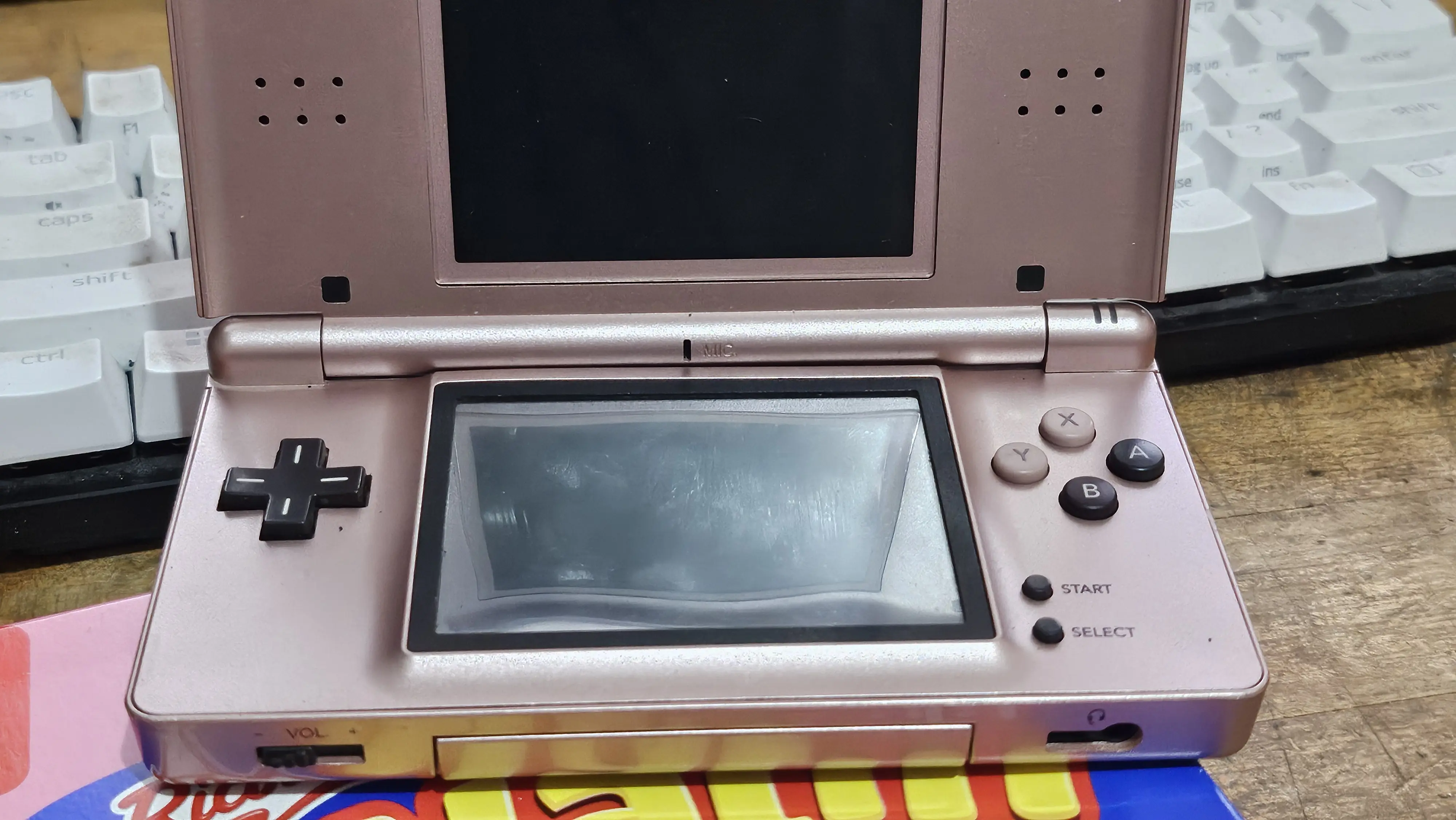
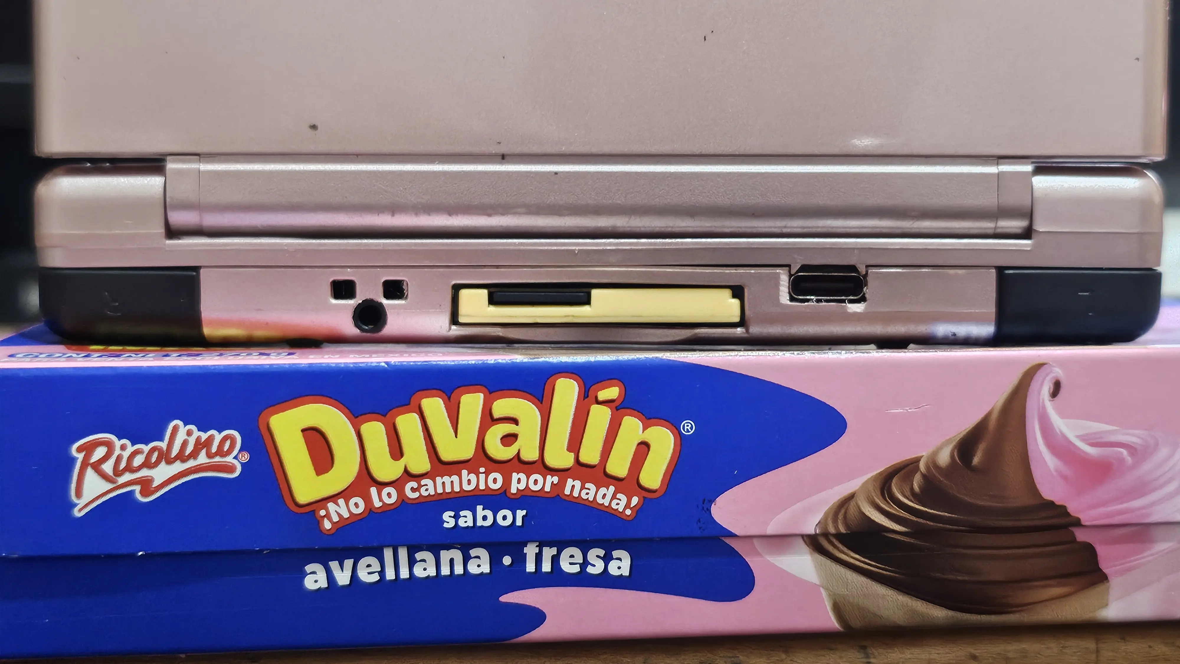
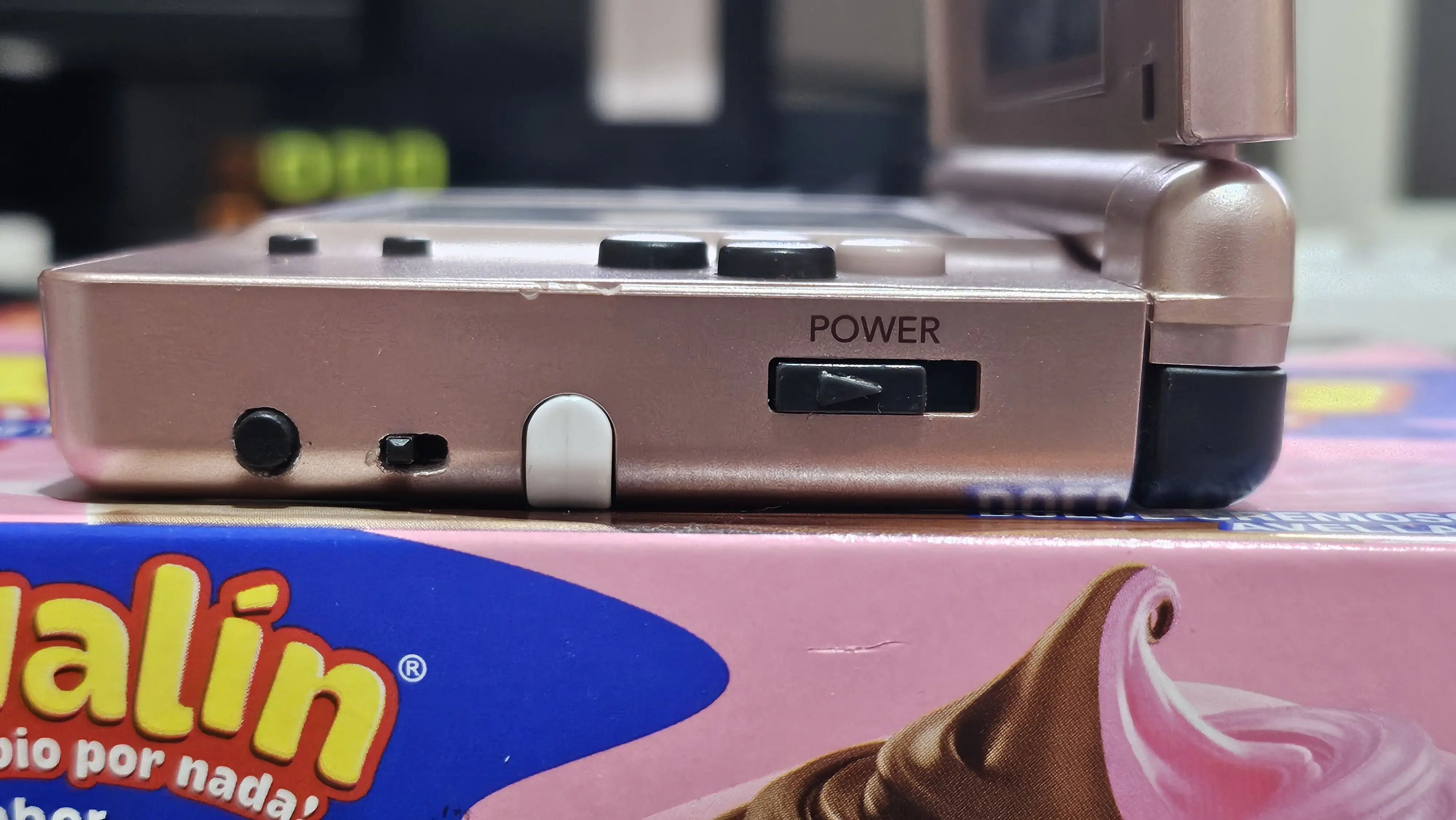
I changed some buttons to give it a cool look, I called it the Duvalin because of the Mexican candy colors and also the fact that there's 2 modes of use.
Final result. -
Credits. -
Thanks to @LCandell, if it wasn't for you, I would've procrastinated this project forever also thanks for the dual Wi-Fi mod I asked you to make for me.
Thanks to my wife, she took care of my child while I was locked on the bench working on this and also thank you for cheering me on all my projects.
Is a DS Lite with the video mod, but I didn't want to lose the upper screen, so I needed to add the dual wifi mod and have 2 different firmwares.
Tools. -
- Hot iron
- Solder wire
- jumper wire
- Flux
- 2-position switch
- 1 push button
- A Dremel tool
- 1 TRSS 2.5mm connector
- UV curable solder mask
- T-7000 Adhesive
- Krazy kola
- A modded Wi-Fi module
- 6 470Ohms resistors
- 4 220Ohms resistors
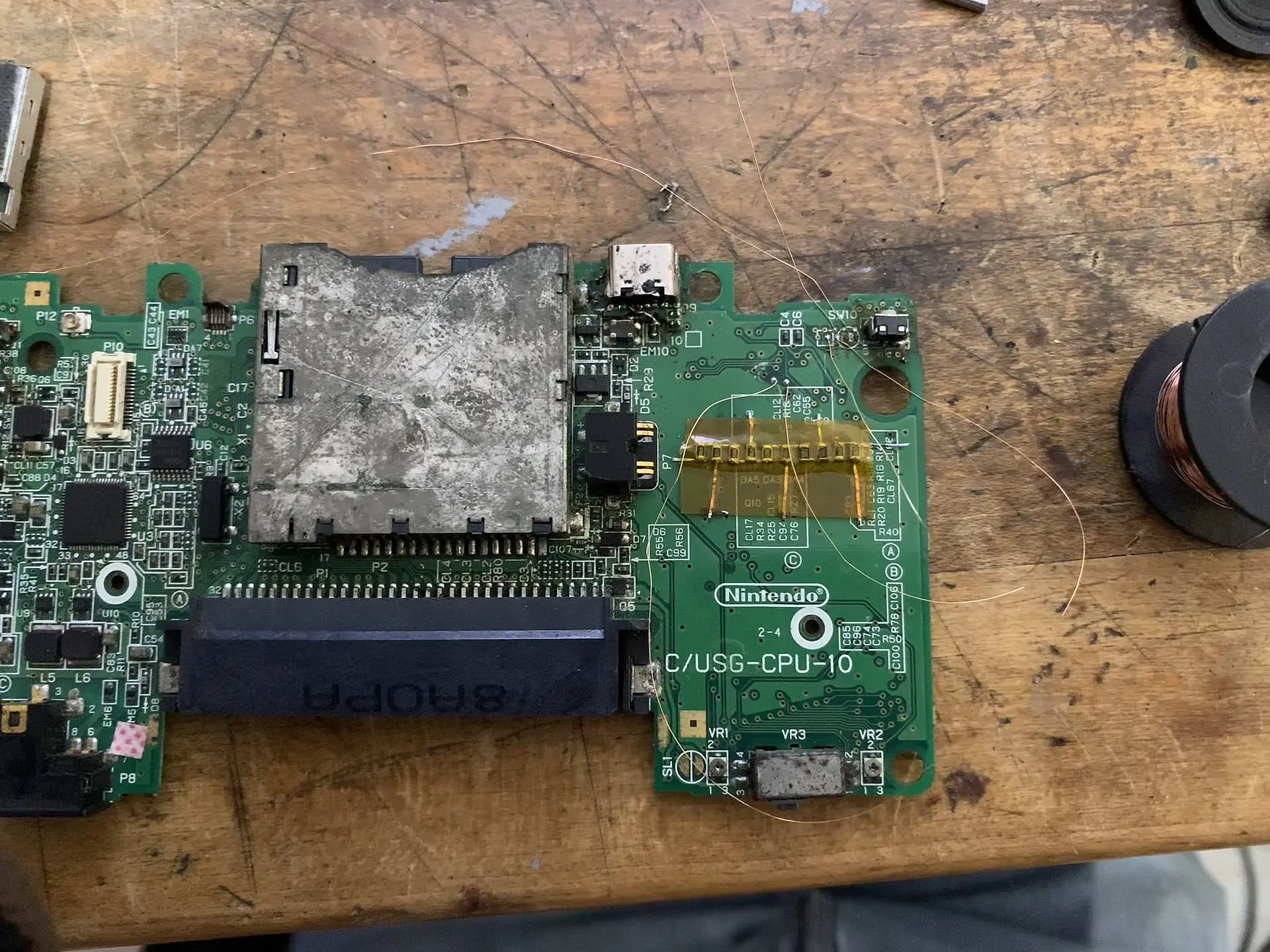
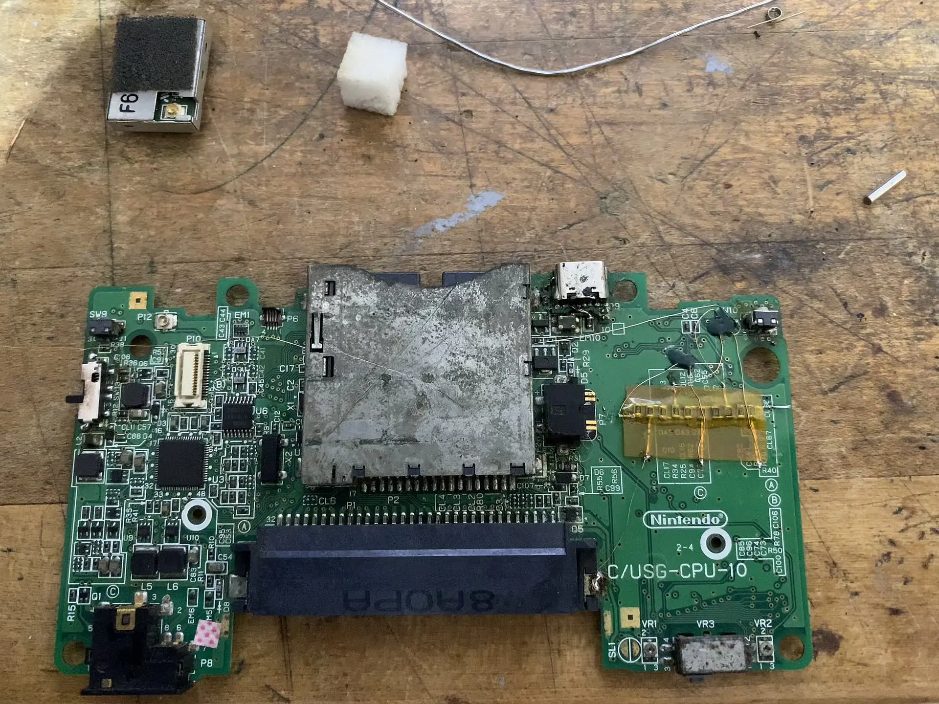
First thing I opened the DS to get to the motherboard, i soldered a circuit made from resistors to get the video signal then cured the soldered pads and VIAs.
I already had a USB-C mod installed. (I know it looks bad but it's working)
Then I tested on other bottom cases so i can plan where to put the 2.5mm connector, the switch and the button.
I liked how it looks on the side of the case, but I tough It was going to be uncomfortable to hold while playing so I decided to put it on the top.
I jumped the video wire to the 2.5mm connector then the GND signal to the motherboard then I soldered SPL0 and SPR0 to the connector (sorry I didn't have pictures of that)
basically, I jumped everything.
The switch's middle terminal is routed to GND also the pushbutton, I broke 1 terminal from the switch because I only needed to short the dual Wi-Fi to GND when I want to use the original firmware, if it is not shorted the ds boots with the video modded firmware.
The pushbutton is routed to P0 signal on the diagram.
I only using the P0 signal button because I don't need the PiP or the transparency functions because I will be using only the screen switching while connected to a screen, when not I can use the two screens.
I changed some buttons to give it a cool look, I called it the Duvalin because of the Mexican candy colors and also the fact that there's 2 modes of use.
Final result. -
Credits. -
Thanks to @LCandell, if it wasn't for you, I would've procrastinated this project forever also thanks for the dual Wi-Fi mod I asked you to make for me.
Thanks to my wife, she took care of my child while I was locked on the bench working on this and also thank you for cheering me on all my projects.