- Joined
- Oct 6, 2021
- Messages
- 26
- Likes
- 29
After completing my first portable project (being my phat PS2) I immediately started working on a follow up with the goal of making it a lot sleeker and A LOT thinner. I decided to do a Wii this time and also decided that I wanted to try my hand at designing my own PCB's for this design. So I started with a feature set that I wanted to include. I wanted
- A dock for the handheld that had HDMI out, 4 gamecube controller ports, built IR LED's for a sensor bar, a memory card port, a USB port, and was able to charge the system while docked
- Flat LiPo battery packs to reduce width
- VGA for the internal screen
- Analog shoulder buttons
- Custom PCB's for minimal wires in the handheld
- NDS Lite buttons and joycon sticks
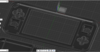
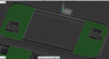
I got to work on the general shape of the handheld. The first part I decided on was these 2 battery packs that I pulled out of a Mophie Powerstation. I came up with the smallest dimensions that could fit the 2 batteries, the standard cooling setup, and a little extra width for rounded corners which is 200x92mm. Already a lot smaller than my PS2 lol. I even had a small little section that would be perfect for fitting my docking connection in. Good start.

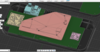
Then I started working on the top portion of the case that would house the screen and controls. Unfortunately, I decided to use most of the boards from the 4-layer store like the PMS-Lite and U-amp, but a day after my order shipped they added the new screen to the store which is exactly what I need for my portable. So I had to make a second order a day later.. Oh well haha. After designing a slot for the screen to fit in I found out that it sticks out exactly the same height that my controller PCB's would be from the base so this means I should be able to use my controller PCB's to fasten the screen down (at least on the edges) which is awesome.


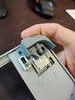
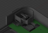
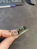
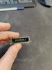
I went back and forth on what type of connection I wanted to use for my console-dock connection. Initially I was going to use a card edge connector on the dock and have some gold fingers on the PCB in the system to connect with. I eventually decided not to do this as a lot of the card edge connectors I looked at were not rated for very many mating cycles and I figured that might potentially be an issue. What I settled on in the end was this -
System side connector
Dock side connector
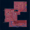
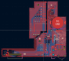
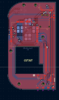
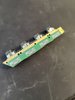
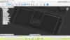
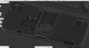
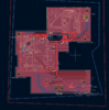
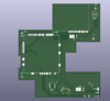
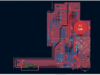
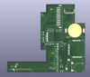
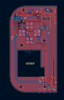
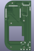
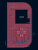
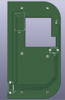
From there I put in a fastener with mounting posts for the Wii and figured out how much room I had to work with for my custom PCB's on the bottom side. Initially I was going to have 1 4-layer PCB that took up the remainder of the room but after seeing a ~$70 price tag I realized that I could just use 2 2-layer PCB's that fit in the 100x100mm options that JLCPCB gives you for super cheap PCB's. So I got the dimensions of the PCB's and got to work learning how to make them with kicad. After a couple weeks I came up with these! I've already ordered these and I really hope that they actually work, I'm just waiting for them to come in now.


If anyone notices anything wrong with these please let me know! I'm totally new to this and this is my first time doing anything like this so I hope it works.
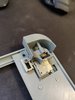
I started designing the mechanism for the shoulder buttons next. I think it'll end up being pretty similar to how the gamecube controller does it but a test print showed that at it least works. I'll have to redesign it a bit to fit overtop of my controller PCB's but I probably won't do that until I actually get them in and see if they work or not. Also, the width of the shoulder buttons will determine the final width of the console itself. Depending on how thick I make them the final product should end up between 20-25mm thick which is perfect I think. I really wanted to use sliding potentiometers with a travel of 5mm for these but I couldn't find any that existed for the life of me. I did find these but they don't seem to be in stock literally anywhere and the free samples I requested from the manufacturer never got a response. So I ended up just going for the same 9mm travel pots that the Ashida uses.
I don't think I'll have room for the Z button on the shoulder itself though without adding a bit of thickness to the console (which I don't want to do) so I'll settle on having it as a face button. And unfortunately, after I already ordered my PCB's I found out that one of the mounting holes is actually in the way of where the button was supposed to be. So I had to shrink the size down a little bit where the mounting hole collided with it.

And that's where I'm at right now! I should be getting my PCB's soon and I'll test 'em out and update when I've made some more progress! So far this is super exciting and I've already got a ton of ideas for what I want to do with my next portable if this one all goes to plan lol. Whenever I end up finishing this I plan on making the whole thing open source as well in case anyone else wants to make one. Just gotta make it myself first.

- A dock for the handheld that had HDMI out, 4 gamecube controller ports, built IR LED's for a sensor bar, a memory card port, a USB port, and was able to charge the system while docked
- Flat LiPo battery packs to reduce width
- VGA for the internal screen
- Analog shoulder buttons
- Custom PCB's for minimal wires in the handheld
- NDS Lite buttons and joycon sticks
I got to work on the general shape of the handheld. The first part I decided on was these 2 battery packs that I pulled out of a Mophie Powerstation. I came up with the smallest dimensions that could fit the 2 batteries, the standard cooling setup, and a little extra width for rounded corners which is 200x92mm. Already a lot smaller than my PS2 lol. I even had a small little section that would be perfect for fitting my docking connection in. Good start.
Then I started working on the top portion of the case that would house the screen and controls. Unfortunately, I decided to use most of the boards from the 4-layer store like the PMS-Lite and U-amp, but a day after my order shipped they added the new screen to the store which is exactly what I need for my portable. So I had to make a second order a day later.. Oh well haha. After designing a slot for the screen to fit in I found out that it sticks out exactly the same height that my controller PCB's would be from the base so this means I should be able to use my controller PCB's to fasten the screen down (at least on the edges) which is awesome.
I went back and forth on what type of connection I wanted to use for my console-dock connection. Initially I was going to use a card edge connector on the dock and have some gold fingers on the PCB in the system to connect with. I eventually decided not to do this as a lot of the card edge connectors I looked at were not rated for very many mating cycles and I figured that might potentially be an issue. What I settled on in the end was this -
System side connector
Dock side connector
From there I put in a fastener with mounting posts for the Wii and figured out how much room I had to work with for my custom PCB's on the bottom side. Initially I was going to have 1 4-layer PCB that took up the remainder of the room but after seeing a ~$70 price tag I realized that I could just use 2 2-layer PCB's that fit in the 100x100mm options that JLCPCB gives you for super cheap PCB's. So I got the dimensions of the PCB's and got to work learning how to make them with kicad. After a couple weeks I came up with these! I've already ordered these and I really hope that they actually work, I'm just waiting for them to come in now.
If anyone notices anything wrong with these please let me know! I'm totally new to this and this is my first time doing anything like this so I hope it works.
I started designing the mechanism for the shoulder buttons next. I think it'll end up being pretty similar to how the gamecube controller does it but a test print showed that at it least works. I'll have to redesign it a bit to fit overtop of my controller PCB's but I probably won't do that until I actually get them in and see if they work or not. Also, the width of the shoulder buttons will determine the final width of the console itself. Depending on how thick I make them the final product should end up between 20-25mm thick which is perfect I think. I really wanted to use sliding potentiometers with a travel of 5mm for these but I couldn't find any that existed for the life of me. I did find these but they don't seem to be in stock literally anywhere and the free samples I requested from the manufacturer never got a response. So I ended up just going for the same 9mm travel pots that the Ashida uses.
I don't think I'll have room for the Z button on the shoulder itself though without adding a bit of thickness to the console (which I don't want to do) so I'll settle on having it as a face button. And unfortunately, after I already ordered my PCB's I found out that one of the mounting holes is actually in the way of where the button was supposed to be. So I had to shrink the size down a little bit where the mounting hole collided with it.
And that's where I'm at right now! I should be getting my PCB's soon and I'll test 'em out and update when I've made some more progress! So far this is super exciting and I've already got a ton of ideas for what I want to do with my next portable if this one all goes to plan lol. Whenever I end up finishing this I plan on making the whole thing open source as well in case anyone else wants to make one. Just gotta make it myself first.
Last edited: