
Bamboo
.
- Joined
- Dec 16, 2017
- Messages
- 13
- Likes
- 20
Hey all! In the middle of portablizing an n64. My first attempt at a project like this and I am more than open to feedback on what I've done and my plans going forward.
Tore apart the board as demonstrated by the bacman videos... wish I hadn't done it that way now because I can't test anything until it's being fed power.... but this was 3 years ago when i started and I didn't know better then lol
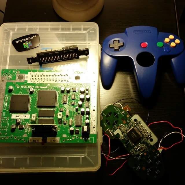
Live and learn!
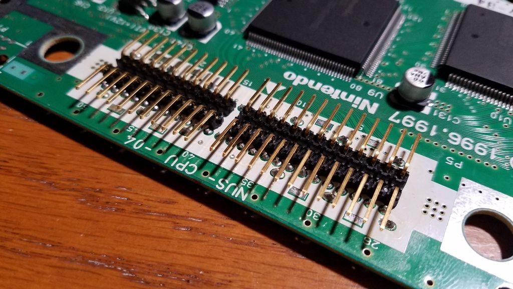
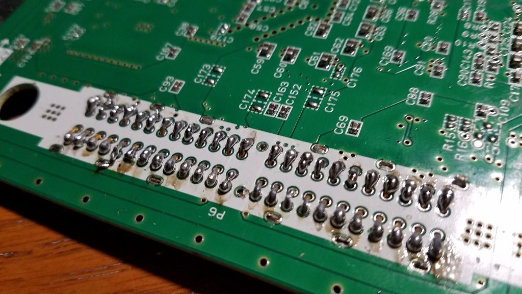
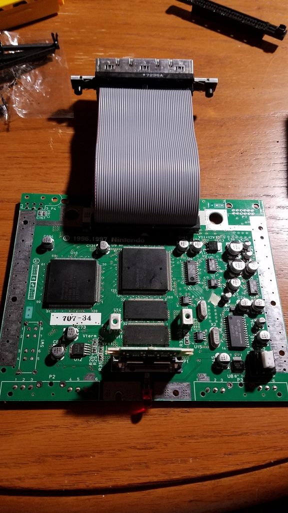
Using a plastic case for screws and stuff I had lying around as the bones of the case. My goal is to create a functional n64p that looks like a big DMG gameboy brick. No board trimming, profile style, straightforward portable. Instead of soldering wires for cartridge relocation, I decided on a "de-location/relocation" hybrid strategy by using right angle header pins bent on the underside of the board and soldered to the contacts where the ext slot pins used to be.
From there I used the 50 pin ide cable to create a harness to go from the header pins to the cartridge slot
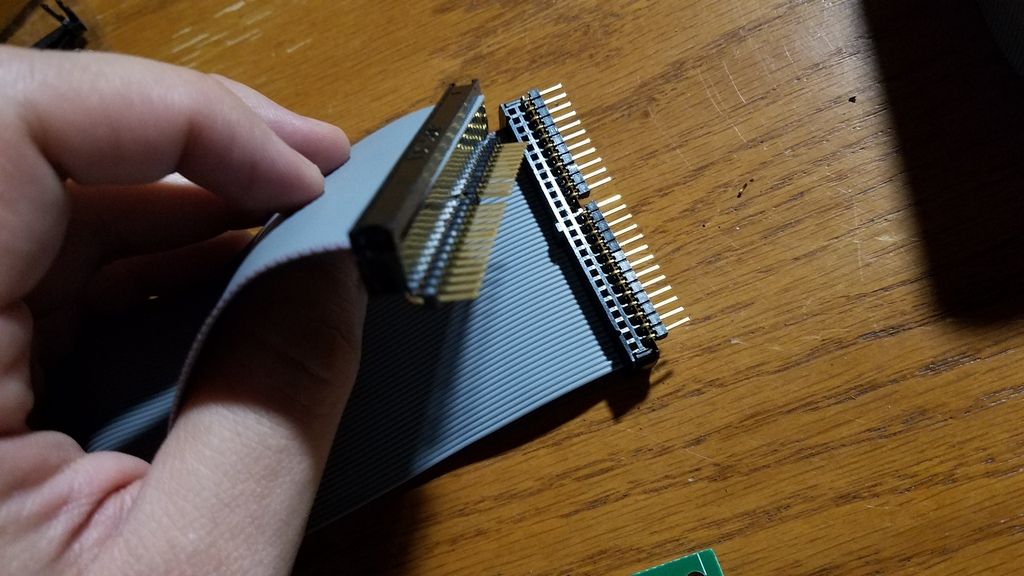
So that's step 1 down. Id like to know your thoughts on that technique and what I plan on doing next.
Next up, I just received my 7" tft LCD pillow back up monitor off Amazon and I'll be stripping it down and wiring up the composite signal/ground to the board shortly. The screen runs on 9-12v so my main power will be li-ion 3sp1 11.1v batteries with protection circuit. I have the pth08080wah, 2k resistor, 100uf cap to step down the power for the 3.3v line.
For charge and play. I'm going to go the safe route and do the dpdt switch as outlined by @ShockSlayer on this site (thanks!)
Using trimmed stock heatsink. Will also connect small fan to flow air.
For audio, I am waiting on the pam8803 which I'll wire to the L/R/5v/ground points on the board. Just received some small speakers suggested in one of the BOMs.
Building in a 1st party controller for now as it is the only one I had readily available and I'm trying to do this whole thing on a budget.
Frankencasing is the name of the game, cannibalizing the old n64 in every imaginable way to make the inner structure this will need. Cleaning it up with bondo and epoxy, sand and paint.
Any thoughtsor insights as I proceed? Ill be posting progress here as I go.
Thanks to everyone who is active in these forums! If not for all the already available info I would have destroyed this thing just trying to open the cover")
Tore apart the board as demonstrated by the bacman videos... wish I hadn't done it that way now because I can't test anything until it's being fed power.... but this was 3 years ago when i started and I didn't know better then lol

Live and learn!
Using a plastic case for screws and stuff I had lying around as the bones of the case. My goal is to create a functional n64p that looks like a big DMG gameboy brick. No board trimming, profile style, straightforward portable. Instead of soldering wires for cartridge relocation, I decided on a "de-location/relocation" hybrid strategy by using right angle header pins bent on the underside of the board and soldered to the contacts where the ext slot pins used to be.


From there I used the 50 pin ide cable to create a harness to go from the header pins to the cartridge slot


So that's step 1 down. Id like to know your thoughts on that technique and what I plan on doing next.
Next up, I just received my 7" tft LCD pillow back up monitor off Amazon and I'll be stripping it down and wiring up the composite signal/ground to the board shortly. The screen runs on 9-12v so my main power will be li-ion 3sp1 11.1v batteries with protection circuit. I have the pth08080wah, 2k resistor, 100uf cap to step down the power for the 3.3v line.
For charge and play. I'm going to go the safe route and do the dpdt switch as outlined by @ShockSlayer on this site (thanks!)
Using trimmed stock heatsink. Will also connect small fan to flow air.
For audio, I am waiting on the pam8803 which I'll wire to the L/R/5v/ground points on the board. Just received some small speakers suggested in one of the BOMs.
Building in a 1st party controller for now as it is the only one I had readily available and I'm trying to do this whole thing on a budget.
Frankencasing is the name of the game, cannibalizing the old n64 in every imaginable way to make the inner structure this will need. Cleaning it up with bondo and epoxy, sand and paint.
Any thoughtsor insights as I proceed? Ill be posting progress here as I go.
Thanks to everyone who is active in these forums! If not for all the already available info I would have destroyed this thing just trying to open the cover
Last edited:


")


