Worklog "We can rebuild him, make him better, compact, and... a Gamecube controller" - Ashida Worklog

Joined
Aug 7, 2022
Messages
3
Likes
3
I figure now's the time to start this thread up, since I'm close to having all the parts I need for my first Wii portable build. I ended up getting 2 of each part so far because from what I've seen, it seems like many newcomers end up messing up parts/boards sometimes, so I figured better safe than sorry, haha. Plus if I end up not ruining too much, I'd have a pretty good head start on a second Ashida! :D

I've populated the Ashida boards I've gotten from 4layertech with pretty much everything they need, and I've just finished up softmodding the 4 layer Wii and got everything up and running smoothly. I've also briefly reviewed the diagrams on the 4layertech website, so I at least have a very rough idea on how a good chunk of the wiring is supposed to be. I just have a couple of lingering questions before I commit to buying the final parts I need.

1.) Do these batteries from the BOM still have the ideal specs for an Ashida Wii portable, or has the community run into other batteries that happen to yield better battery life since the BOM was created? https://mabdelectronics.com/product...0mah-high-drain-flat-top-rechargeable-battery

2.) So far, I've yet to use magnet wire for anything previous soldering projects. Is magnet wire completely necessary, or does it just happen to be advantageous space-wise due to the sheer number of wires needed to connect everything up? I do have a ton of 28awg ribbon wire, but I'll totally grab some magnet wire if the pros of using it in this build are just too good to ignore. Also what gauge magnet wire is generally considered ideal for an Ashida portable? I see the trimming guide says using 34-38awg magnet wire for the USB lines is fine, so would commiting to just 34awg be good for everything on the portable (aside from power/gnd of course), or are there scenarios where thinner wire ends up being better?

3.) Kind of piggybacking off of question 2, but from my searching around, it also seems like several video/audio lines (and maybe others) need to be shielded to avoid noise. Would this also play into magnet wire being preferred due to how tightly you can twist the ground line around the signal line? Also what lines need to be shielded exactly? Just the audio/video lines, the MC line, and USB lines? Or are there others I should consider twisting ground wires around?

4.) So I have a test print of the shell from a friend of mine, and looking at the spot for the LED confuses me a little bit. Am I supposed to drill out a spot so the LED is visible from the outside of the shell, or is it intended to be slightly visible through the plastic shell itself? My shell is going to be indigo, so I'm not sure it would show up as well as it would for something like a white shell (or a clear one).

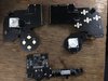
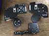
I'll likely add more questions to this thread later as they come up. In the meantime, I might as well post my populated Ashida boards that I've been able to finish up tonight. Really excited to attempt diving into the bulk of the build soon! I should be attempting to trim my Wii some time this week.
 

Attachments

Joined
Jul 9, 2020
Messages
227
Likes
499
1.) Do these batteries from the BOM still have the ideal specs for an Ashida Wii portable, or has the community run into other batteries that happen to yield better battery life since the BOM was created? https://mabdelectronics.com/product...0mah-high-drain-flat-top-rechargeable-battery
Any 12700 battery will do the job for the most part. I usually go for the highest mah available.

2.) So far, I've yet to use magnet wire for anything previous soldering projects. Is magnet wire completely necessary, or does it just happen to be advantageous space-wise due to the sheer number of wires needed to connect everything up? I do have a ton of 28awg ribbon wire, but I'll totally grab some magnet wire if the pros of using it in this build are just too good to ignore. Also what gauge magnet wire is generally considered ideal for an Ashida portable? I see the trimming guide says using 34-38awg magnet wire for the USB lines is fine, so would commiting to just 34awg be good for everything on the portable (aside from power/gnd of course), or are there scenarios where thinner wire ends up being better?
3.) Kind of piggybacking off of question 2, but from my searching around, it also seems like several video/audio lines (and maybe others) need to be shielded to avoid noise. Would this also play into magnet wire being preferred due to how tightly you can twist the ground line around the signal line? Also what lines need to be shielded exactly? Just the audio/video lines, the MC line, and USB lines? Or are there others I should consider twisting ground wires around?
Q2: 34awg or 38awg magnet wire is pretty essential for the via wiring necessary for this project. Don't be afraid of it... just use solder to melt the enamel off of the tip and snip it to about 1mm exposure. Stick it in the via thats been scratched to remove solder mask and use your finest tip iron to make a nice fillet on that via with the wire in the hole. That is the most secure way to do these connections. Also, you need magnet wire for twisted pairs as the insulation of regular wire is not thin enough for the diff pairs.

I would just go 34awg. Get various colors. Atleast two... red and green is what i started with. If you have one color you can mark one of the strands with sharpie before twisting but thats a pain in the butt.

Q3: If you are using DD or HDMI mod you will definitely need to twist the 54mhz line with ground. For good measure i also do that with GCD, MC for audio. USB lines are twisted with eachother, not ground. If you are running a bunch of i2c stuff i've had to also twist sda and scl with ground to get DD to work with all features. Do NOT twist SDA and SCL with each other; this will cause weird issues and should be avoided.

4.) So I have a test print of the shell from a friend of mine, and looking at the spot for the LED confuses me a little bit. Am I supposed to drill out a spot so the LED is visible from the outside of the shell, or is it intended to be slightly visible through the plastic shell itself? My shell is going to be indigo, so I'm not sure it would show up as well as it would for something like a white shell (or a clear one).
If your shell is made of certain materials the LED will shine through well enough to convey their indication. For more solid materials I will stick a tiny pin hole to start and then drill a very small hole. I will fill it with hot glue from the back side with kapton over the hole in the front to stop seeping. This makes a mini lens diffuser thing. Not necessary but I like it. If you have the clear shell just glue the LED in the hole. It will fit the addressable LED that comes with the PMS2/LITE... My first ashida i just left out the light. But Im glad the subsequent ones have had it.

Ashida is a really great build. Thinking back, the tricky things i can remember are:

-Interference with most systems. Shield what signals you can...

-MX chip relocation works really well covered in kapton and hot glued to the LDO area

- Scratch bluetooth traces before you solder any wires to the trim... trust me.

- build a switch to lift the + wire from the PMS. Or just make sure to take out batteries before testing or futzing around in there. Magic smoke is not fun to see.

- Be careful with the threads on the holes that hold each wing pcb to the case. These are not really mechanically functional. They just hold the pcb in place and the post on the back side actually hold the boards down while you press the buttons and pads. Wrench em down and lose the post. Its a pain for the rest of the build lol

- Just wire the speakers to the pads and call it a day. The spring fit has never been reliable enough in my experience.


Hope that gets you started on the right foot. Good luck mate!

CHEERS!
 
Joined
Aug 7, 2022
Messages
3
Likes
3
Been busy with a lot of stuff this week (and melting due to the heatwave), but thank you so much for the detailed reply SparkleBear! I've gone ahead and ordered 2 different colors of 34AWG magnet wire, as to not open the possibility of me confusing two wires together in the future.

"Scratch bluetooth traces before you solder any wires to the trim... trust me."

I don't think I'll be doing a bluetooth relocation, should I still sever bluetooth traces?

Also I should probably mention I'll be building this Ashida specifically with the RVL-PMS-Lite, the RVL-AMP, and the driver board that comes with the current IPS screen being sold on 4layertech right now. Will I need to keep in mind any special steps or alterations from a standard Wii Portable build to accommodate these parts, since they're somewhat different from the parts used in current guides due to the chip shortage?

EDIT: I decided to review the documentation of those boards a bit more thoroughly this time, and noticed it mentions to *not* remove the LDO, but still hook up the 1.8v line to the PMS-Lite. It also seems like there's a bit of extra wiring if you want to use the potentiometer for volume with the RVL-AMP? Is there anything else to that other than wiring it to the PMS-Lite per Figure 4 on the RVL-Amp documentation page?

Is there anything else different that I may have missed, or maybe isn't explicitly stated in the Documents tabs for the newer boards?
 
Last edited:

Revine

.
Joined
Jun 26, 2022
Messages
15
Likes
10
Been busy with a lot of stuff this week (and melting due to the heatwave), but thank you so much for the detailed reply SparkleBear! I've gone ahead and ordered 2 different colors of 34AWG magnet wire, as to not open the possibility of me confusing two wires together in the future.

"Scratch bluetooth traces before you solder any wires to the trim... trust me."

I don't think I'll be doing a bluetooth relocation, should I still sever bluetooth traces?

Also I should probably mention I'll be building this Ashida specifically with the RVL-PMS-Lite, the RVL-AMP, and the driver board that comes with the current IPS screen being sold on 4layertech right now. Will I need to keep in mind any special steps or alterations from a standard Wii Portable build to accommodate these parts, since they're somewhat different from the parts used in current guides due to the chip shortage?

EDIT: I decided to review the documentation of those boards a bit more thoroughly this time, and noticed it mentions to *not* remove the LDO, but still hook up the 1.8v line to the PMS-Lite. It also seems like there's a bit of extra wiring if you want to use the potentiometer for volume with the RVL-AMP? Is there anything else to that other than wiring it to the PMS-Lite per Figure 4 on the RVL-Amp documentation page?

Is there anything else different that I may have missed, or maybe isn't explicitly stated in the Documents tabs for the newer boards?
The Ashida uses an RVL-PMS-Lite so you're fine there, and the RVL-Amp was specifically designed to be working for Wii Portables such as the Ashida, while the U-Amp was made for more than just Wii Portables
 

Stitches

2 and a Half Dollarydoos
Staff member
.
.
Joined
Feb 5, 2017
Messages
3,854
Likes
3,026
Location
Banana Bender Land, Australia
Portables
6
Been busy with a lot of stuff this week (and melting due to the heatwave), but thank you so much for the detailed reply SparkleBear! I've gone ahead and ordered 2 different colors of 34AWG magnet wire, as to not open the possibility of me confusing two wires together in the future.

"Scratch bluetooth traces before you solder any wires to the trim... trust me."

I don't think I'll be doing a bluetooth relocation, should I still sever bluetooth traces?

Also I should probably mention I'll be building this Ashida specifically with the RVL-PMS-Lite, the RVL-AMP, and the driver board that comes with the current IPS screen being sold on 4layertech right now. Will I need to keep in mind any special steps or alterations from a standard Wii Portable build to accommodate these parts, since they're somewhat different from the parts used in current guides due to the chip shortage?

EDIT: I decided to review the documentation of those boards a bit more thoroughly this time, and noticed it mentions to *not* remove the LDO, but still hook up the 1.8v line to the PMS-Lite. It also seems like there's a bit of extra wiring if you want to use the potentiometer for volume with the RVL-AMP? Is there anything else to that other than wiring it to the PMS-Lite per Figure 4 on the RVL-Amp documentation page?

Is there anything else different that I may have missed, or maybe isn't explicitly stated in the Documents tabs for the newer boards?
The RVL-Amp works a bit differently to the U-Amp, and it needs a PMS updated with the latest firmware to interpret the analog volume wheel. Afaik the only extra step you need to follow is to run a data wire from the middle leg of the audio wheel to one of the ADC pads on the PMS. There's a diagram of where those ADC pads are in the RVL-Amp documents tab
 
Joined
Jul 24, 2022
Messages
21
Likes
8
Location
uk
Portables
Building One
Been busy with a lot of stuff this week (and melting due to the heatwave), but thank you so much for the detailed reply SparkleBear! I've gone ahead and ordered 2 different colors of 34AWG magnet wire, as to not open the possibility of me confusing two wires together in the future.

"Scratch bluetooth traces before you solder any wires to the trim... trust me."

I don't think I'll be doing a bluetooth relocation, should I still sever bluetooth traces?

Also I should probably mention I'll be building this Ashida specifically with the RVL-PMS-Lite, the RVL-AMP, and the driver board that comes with the current IPS screen being sold on 4layertech right now. Will I need to keep in mind any special steps or alterations from a standard Wii Portable build to accommodate these parts, since they're somewhat different from the parts used in current guides due to the chip shortage?

EDIT: I decided to review the documentation of those boards a bit more thoroughly this time, and noticed it mentions to *not* remove the LDO, but still hook up the 1.8v line to the PMS-Lite. It also seems like there's a bit of extra wiring if you want to use the potentiometer for volume with the RVL-AMP? Is there anything else to that other than wiring it to the PMS-Lite per Figure 4 on the RVL-Amp documentation page?

Is there anything else different that I may have missed, or maybe isn't explicitly stated in the Documents tabs for the newer boards?
I’m pretty sure for the bluetooth traces, scratching the board is to just get rid of the soldermask so you can solder directly to the traces.
 
Top