Worklog Unnamed Portable

Joined
Mar 22, 2021
Messages
55
Likes
13
Location
Germany
Been working on this portable since about a year ago when I started to learn Kicad and PCB design because I could not find the regs for the PMS V1 so I redesigned for different regs.
Its currently unnamed as I am not creative enough to think of a name.

Trimming went relatively smoothly, but I had a bit of trouble with getting the resistances down. This was solved by removing some components on the edges and sanding at angle.
IMG_20220224_193835.jpg
IMG_20220224_193850.jpg

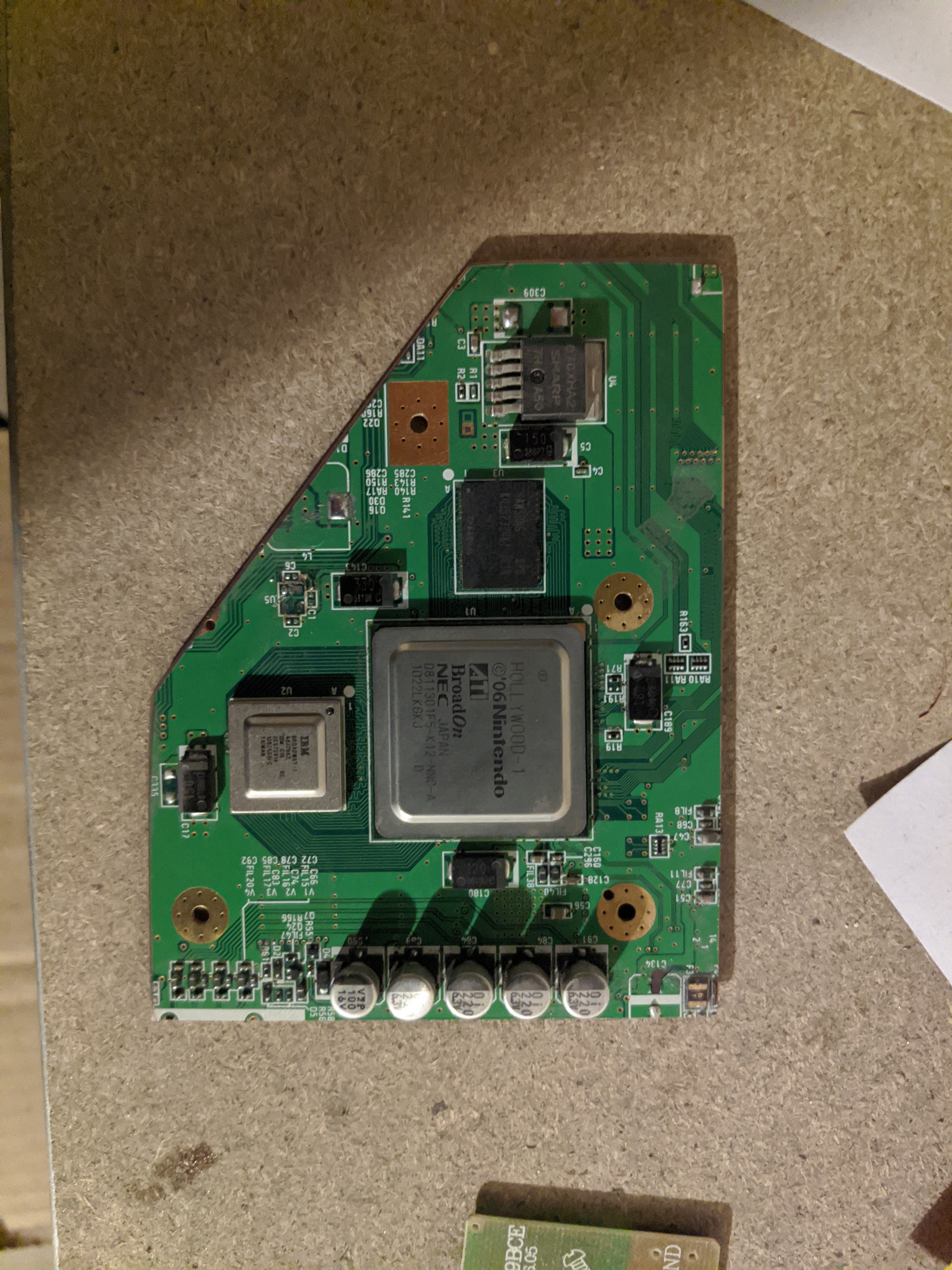
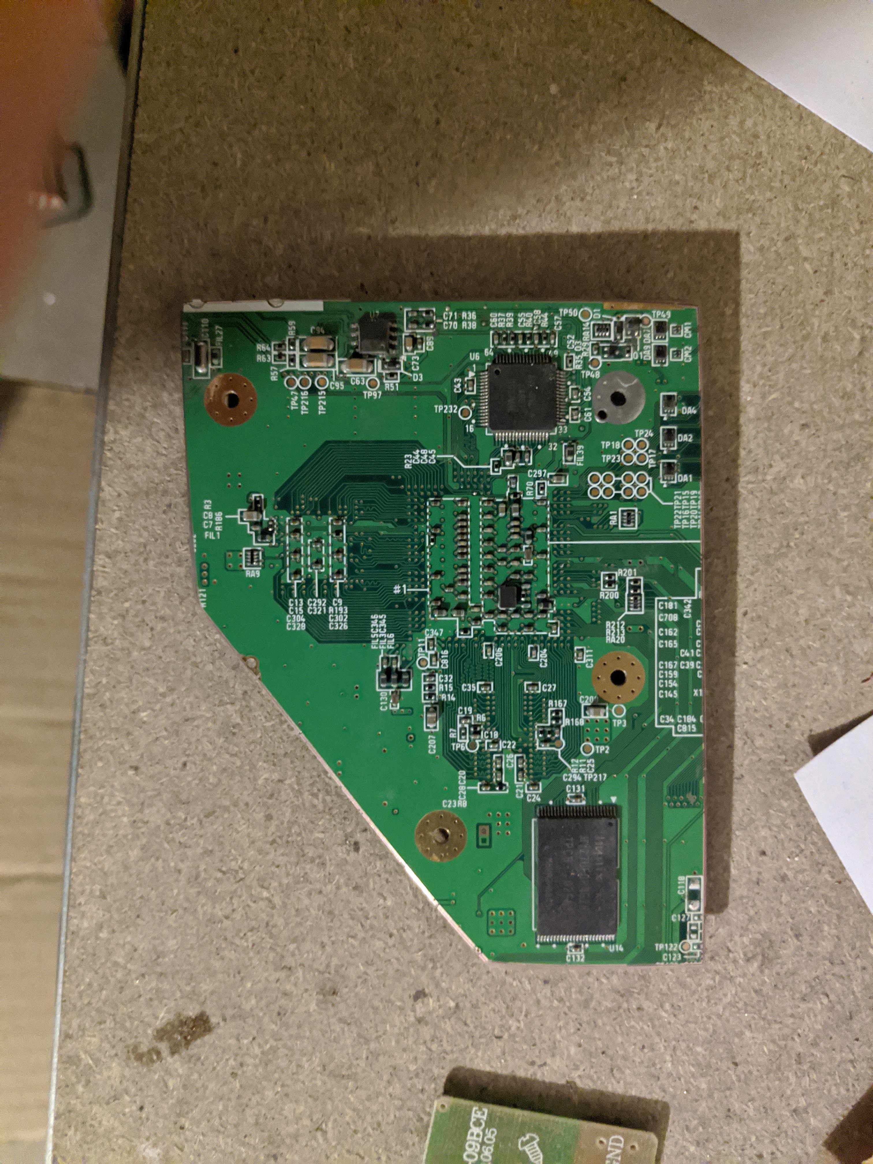
I know I could propably trim the board a lot smaller but I really didnt want to accidentally cut through any important traces.

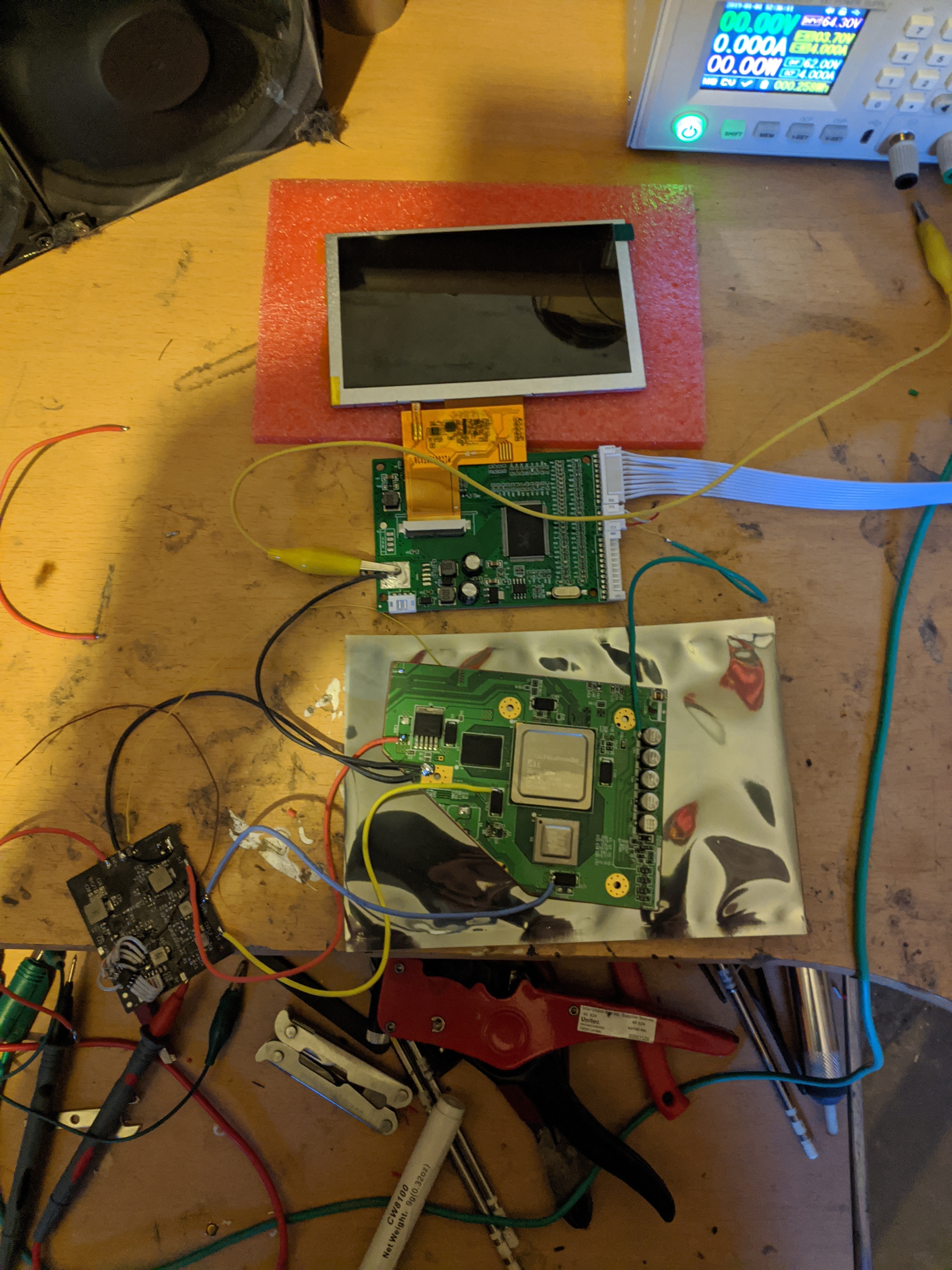
And it does indeed boot!
I have however encountered a *slight* problem:
The screen and the Wii cant be powered on together.
The Wii boots and the screen starts, displays for a fraction of a second and then restarts.
At first I thought that I might be drawing too much current on the 3v3 line so I went and bought this step down reg and connected it to my 5v supply but the same ptoblem still occurs!

If anyone has an idea of what could be the problem please leave a message!

IMG_20220228_155731.jpg
 
Joined
Mar 22, 2021
Messages
55
Likes
13
Location
Germany
Might have phrased it a bit weird, the problem is that the Wii stays powered on but the screen flickers on and off and I dont actually need a 1.8v connection as I havent removed the LDO.
Thanks for the help though.
 
Joined
Jun 3, 2019
Messages
142
Likes
118
Is the wii is working with another screen and something else is working with this screen?
 
Joined
Mar 22, 2021
Messages
55
Likes
13
Location
Germany
Yup both are confirmed to be working so I think that I might need to revise my power regulation circuitry
 
Joined
Mar 22, 2021
Messages
55
Likes
13
Location
Germany
I'm finally having time again to work on this portable after a *little* break to focus on exams/other stuff and made a bunch of progress and encountered a new issue.

I managed to get a proper output of the "RVloader bootloader 01" screen but then the screen starts to display a pink image and flickers on and off. I have attached a video demonstrating this problem and a screenshot of the RVloader screen.

Is this an issue with the USB not being connected or is it something to do with the GPU / U10?


Screenshot_20220518-184957_Fotos.png


I was also able to make a button/gc+2.0 combo board which I am going to order in the next couple of days.
Button Board — Leiterplatteneditor 18.05.2022 19_01_31.png

3D-Betrachter 18.05.2022 19_02_04.png

3D-Betrachter 18.05.2022 19_02_17.png
 

Viilmo

.
Joined
Jun 23, 2021
Messages
208
Likes
92
Location
Germany
Portables
1
I'm finally having time again to work on this portable after a *little* break to focus on exams/other stuff and made a bunch of progress and encountered a new issue.

I managed to get a proper output of the "RVloader bootloader 01" screen but then the screen starts to display a pink image and flickers on and off. I have attached a video demonstrating this problem and a screenshot of the RVloader screen.

Is this an issue with the USB not being connected or is it something to do with the GPU / U10?


View attachment 22592

I was also able to make a button/gc+2.0 combo board which I am going to order in the next couple of days.
View attachment 22594
View attachment 22595
View attachment 22593
Can you post pics of the u10 wiring?
 
Joined
Mar 22, 2021
Messages
55
Likes
13
Location
Germany
IMG_20220518_212831.jpg

(U10 is the bottom right chip and the thin yellow wire above it is its wire)
IMG_20220518_212946.jpg

IMG_20220518_212857.jpg

I might try cutting the wire a bit shorter and see if that helps.
 

Viilmo

.
Joined
Jun 23, 2021
Messages
208
Likes
92
Location
Germany
Portables
1
I don't see anything wrong, how did you unsolder the u10. Might have been damaged in the process.
 

Viilmo

.
Joined
Jun 23, 2021
Messages
208
Likes
92
Location
Germany
Portables
1
Maybe try it with u9. Could be it got damaged somehow. I've also heard that some said theirs worked after they switched to magnet wire.
 
Last edited:
Joined
Mar 22, 2021
Messages
55
Likes
13
Location
Germany
Swapping the chip out with U9 worked and its fully booting now!
The only problem right now is with the 3.3v regulator I put on my custom WiiPMS isnt able to output enough current for the WIi and screen and I think thats because I have it directly connected to the VSYS(3.7v) of the BQ chip. To atleast somwhow power the screen I currently have it hooked up to an LDO I had lying around. I'm going to try and cut the trace to the reg and connect it to the output of my 5v regulator instead and see if that helps.
 

Viilmo

.
Joined
Jun 23, 2021
Messages
208
Likes
92
Location
Germany
Portables
1
Swapping the chip out with U9 worked and its fully booting now!
The only problem right now is with the 3.3v regulator I put on my custom WiiPMS isnt able to output enough current for the WIi and screen and I think thats because I have it directly connected to the VSYS(3.7v) of the BQ chip. To atleast somwhow power the screen I currently have it hooked up to an LDO I had lying around. I'm going to try and cut the trace to the reg and connect it to the output of my 5v regulator instead and see if that helps.
Great to hear
 
Top