
trimmed a little to much my pms has a short on the 1.25v rail.
Last edited:
Ok thank you man I’ll give it a try today hopefully it works.View attachment 21823
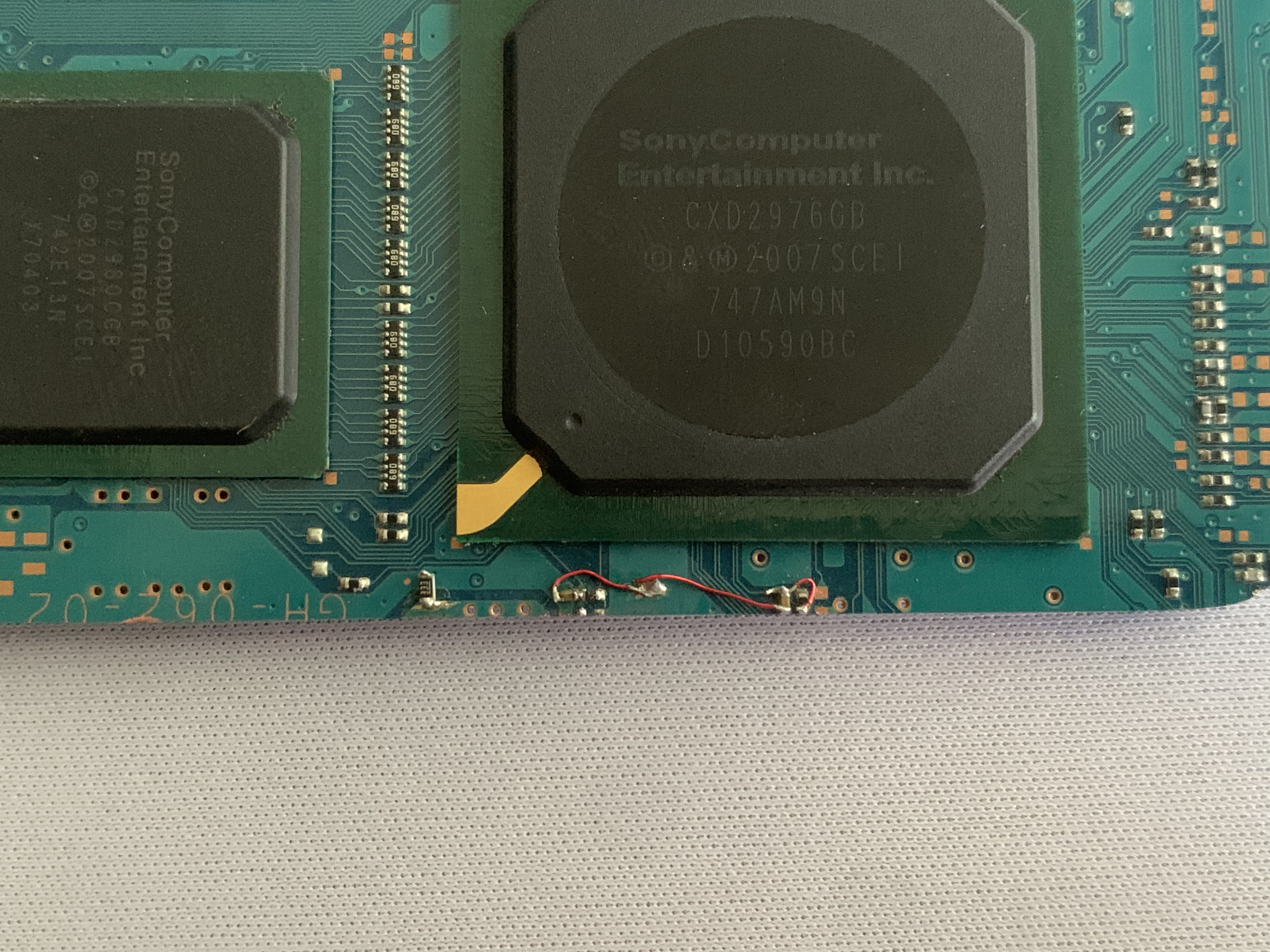
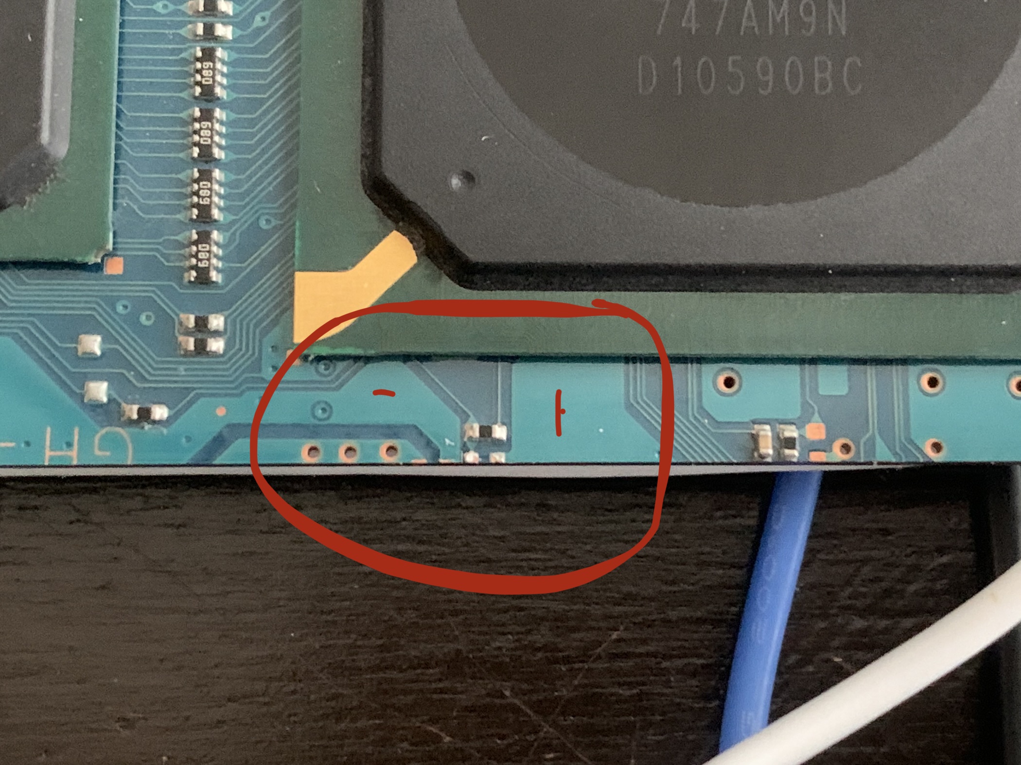
To make it easier for you, remove this capacitor from the board that has it, and place it on the board that is not working, as I indicated. This capacitor that is on the working board will not be needed if you remove it and put it on the other one.
On what pins the right side ?Wait a minute, I took a better look at the mapping, the photo you sent me couldn't see the details, it doesn't really connect to this track.