Discussion Think a Via Data board like this could be useful/Possible?

MJMT

.
Joined
Apr 16, 2021
Messages
88
Likes
118
Portables
2
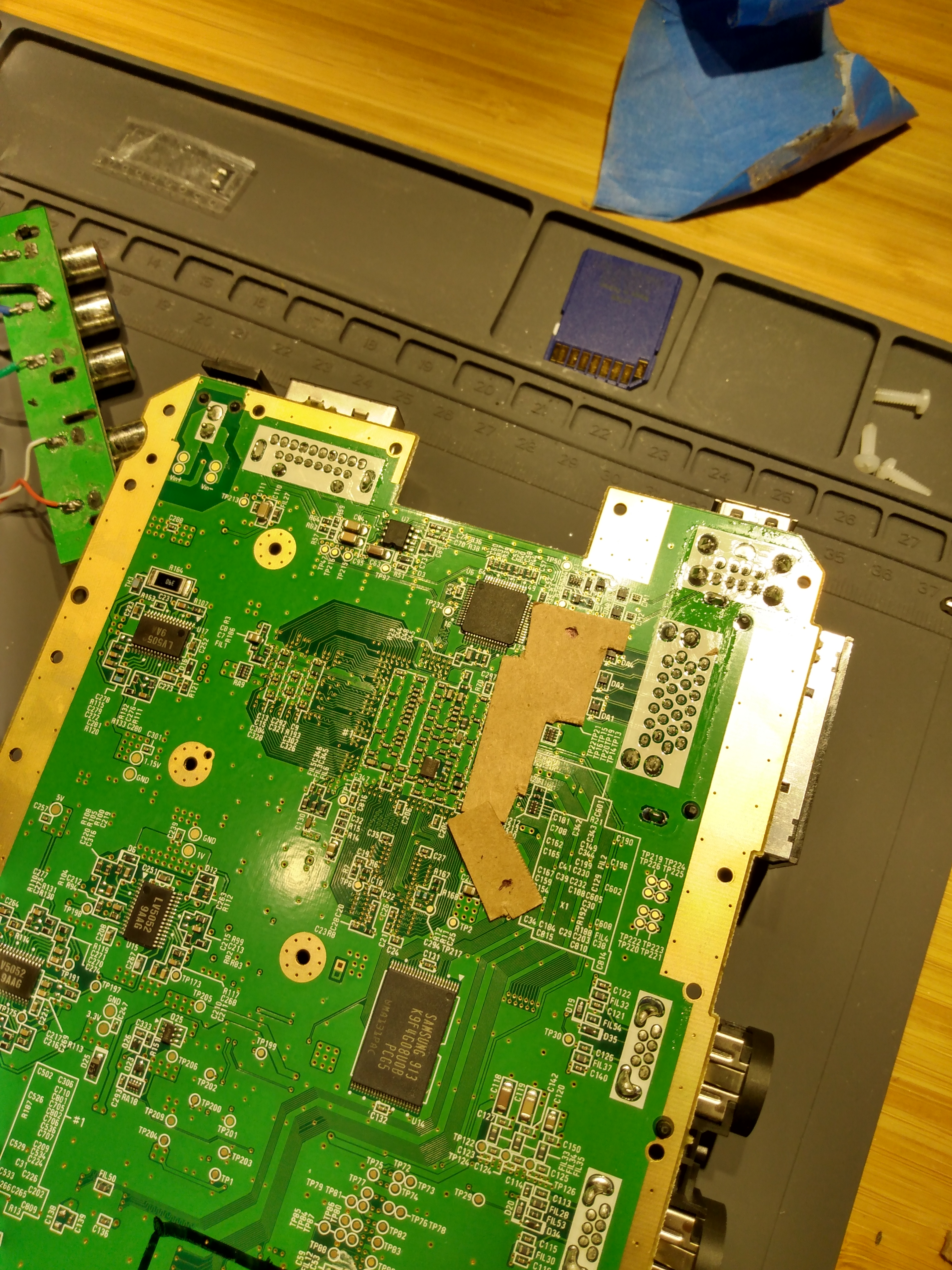
I was just thinking about a way to make that cluster of Vias on the back of the board easier to deal with. If I could make a board this small that is designed to fit in this area and put a few molex connectors on it. That would make for a nice stable and clean base to work with. I was thinking I could use like 32-34 AWG Bus wire/ Uncoated magnet wire straight through to the "Data Board" with it's own Vias which will be lined up.

IMG_20220419_182817849_HDR.jpg
IMG_20220419_184943844.jpg
 

MJMT

.
Joined
Apr 16, 2021
Messages
88
Likes
118
Portables
2
Nah. Just your plain Jane off the shelf 2-part K-Mart PCB. I also went economy on the shipping so it'll be a bit before the next update. I expect to be modifications due to poor measurements. I'll post the pictures of it connected to 1 of my boards when the time comes.
 
Joined
Jul 9, 2020
Messages
227
Likes
498
I imagine it’s gonna be tough to mate the vias to the hard pcb. You might want to feed magnet through the vias first and then through your pcb to ensure electrical connection… or use the first proto to make sure alignment is good then produce it in flex. I love the idea I just don’t know if it will work as a non flex pcb
 

MJMT

.
Joined
Apr 16, 2021
Messages
88
Likes
118
Portables
2
I was going to solder the all the vias connections on the trimmed board and feed it through the holes. I have no experience making a flex PCB. maybe I can look into it more after this.
 
Last edited:

MJMT

.
Joined
Apr 16, 2021
Messages
88
Likes
118
Portables
2
No

I'll hook up a printer right now ;0

Edit: 9:28 PM EST- looks pretty good except for 1 of the easiest parts. I had the left ground pad measurement and I swore it was in the right place but it is very WRONG. the Vias seem good but it's hard to tell given the .5mm between most and the .3mm for the controllers ;0. The program wouldn't let me run wires directly to those .3mm vias. Is there a way to format the board to allow me to do that or is it a tracer size requirement? Nintendo did it so I should be able to as well.
DataboardMockup3.png
 

Attachments

Last edited:

MJMT

.
Joined
Apr 16, 2021
Messages
88
Likes
118
Portables
2
Got my initial board batch. I'll check them tomorrow to see how things line up.

Edit: An initial look shows me several things must be tweaked.
Edit 2: This is a modification based on what I saw (Removed for your safety)
They drilled the holes really badly but I think they might be so small that they need to be done by laser or something.

DataboardOSH1v2.png

Edit 3: It might be better to cut out areas for the wires as large ovals and just put test points on the surface to solder to for manufacturing purposes. I'll try to make a new design like that.
 
Last edited:
Top