Question The USB CM1/CM2 Traces and a USB breakout board question

Joined
Feb 21, 2020
Messages
24
Likes
11
Just want to say that I'm very close to being able to boot a real game off of a real wii that is trimmed and I am eternally grateful for y'all patience with me!
All I have left to re-connect is controller ports and USB ports! Story time:

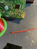
So I had the unfortunate experience of lopping off my USB ports despite wanting to keep them because in the middle of the trim I thought "Something must be wrong. is it because I left the usb ports on and they're causing a short or something?

Long story short, no, I was just being impatient and did a poor U10 relocation that didn't sit well. I bought these usb breakout boards in hopes to breath usb drive reading life into my trimmed wii, they seem like they'll do the trick, they have a voltage trace, a D+ and a D-, and a ground. Seems like it correlates to the stuff on the wii!

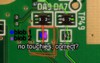
Anyways, The CM1 and CM2 bit of the underside of the board:

1) There's a 2x2 grid of metal bits on them. Based on what I've seen in Manolo's Wii trimming video... these things are small. Comically small. I know that people have suggested magnet wire for soldering to traces, but is this an acceptable place for magnet wire? I have 34 AWG magnet wire that's enamel coated. If they're enamel coated, should I try to burn the enamel off? or is twisting them and separating them at the D+ and D-, and the CM1/2 enough to stop interference despite their enamel or does the enamel just nullify wire contact?
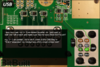
2) I read that one would have to twist what I can only assume is the D+ and D- line of a USB port together (in the guide it says "Line 6 must be twisted with line 7, and line 3 must be twisted with line 2"), if I just want one port to work, am I just going to solder line 3 to the left half and line 2 to theright half? (Again, using a different boardwith D+ and D-, does the placement matter here or is it sufficient that they are just both occupying one half of the CM component without making contact?

So basically I think my essential questions are:

1. Is the enamel coating of magnet wire going to mess me up here when I try to twist wires together
2.The wires must be separated at the USB board and the CM component, yes? otherwise they're twisted together?
3. Soldering to the CM component, the wires must be separated vertically, as in I can place a vertical line down the center and those points don't contact?
1673752251678.png
4.Do we know which points (2 and 3 or 6 and 7, for example) correlate to a D+ and a D-?

Here's another image for what I'm referring to!
1673751694796.png
 

Stitches

2 and a Half Dollarydoos
Staff member
.
.
Joined
Feb 5, 2017
Messages
3,864
Likes
3,032
Location
Banana Bender Land, Australia
Portables
6
The enamel coating is quite flexible, you can twist the wires together no issue. When soldering the wires, you just make a little blob of solder on the end of your iron and poke the end of the wire into the blob for a few seconds. It'll burn off the enamel just where the blob is, and you only need to expose 2mm of wire to get the job done.

The twisting of the wires is to reduce difference of interference in the data wires. You can leave 5mm of the ends of a pair untwisted to make soldering easier, it won't break anything.

Lines 6 & 2 are D-, and lines 7 & 3 are D+. They are colour coded, but it could stand to have a direct mention in the legend.

What you've drawn is correct for the CM components too. Ideally you'd solder the wires to just the lower end of the component (relative to the images), but that method works too. Just do the blobbing on the sides rather than the top to reduce the chance of the blobs shorting together.

Also you can skip the CM components and solder straight to the vias if you're using an internal drive system, like the RVL-PD2. Using the CM components is mainly for external port static protection.
 
Joined
Feb 21, 2020
Messages
24
Likes
11
Blurry, but, I think I'm gonna have to retire this board. I am feeling incredibly demoralized lol.

I spent the better half of 4 hours trying to blob solder onto a side of the cm1 with 34 AWG magnet wire, and I think my lack of experience in soldering is simply too much of a weakness here.

When that failed, I tried the cm2. I think I burned the contacts off of both CM1 and CM2 and I even tried wiring to tracesto see if I could get anything other than bbloaders "no usb drive" error message.

1673895720285.png

Pictured above is the wire I was trying to use, I could tin it, I could get the metal exposed, but I just have no idea how to verify it's "working" other than soldering D+, D-, Vbus, and GND and then praying. The picture is also blurry, but those components are no longer on the board and I don't actually feel confident enough to re... solder? place? them

I have a dead board that had another CM1 I was gonna see if I could just "resolder" like I did with U10 relocation, but I think it's just not in the cards for me here. I don't think I understand *why* I couldn't blob solder on the side? but it just wouldn't take, or the wire would have the weakest connection and a breeze would roll on by.

I even tried using sturdier wire (or at least wire that vaguely resembled manolo's "new wii trimming guide" video I linked above in the OP, I don't have a picture of the wiring job, just a picture of the board sans small components.

I tried holding things in place with hot glue and other stuff, but I'm just like, super demoralized.

I'm happy I posted, happy I got an answer, but I think the best course for me here is to just try again with another board and not chop off the usb port ;~;7

I guess my last question is, am I dead here? I think the answer is yes until I learn to solder better.
Anyways, thanks for coming to my ted talk!
 

Attachments

Last edited:

Stitches

2 and a Half Dollarydoos
Staff member
.
.
Joined
Feb 5, 2017
Messages
3,864
Likes
3,032
Location
Banana Bender Land, Australia
Portables
6
Woah, that wire is way too thick for soldering to vias. Data lines don't need to be that thicc, magnet wire is fine.

As for the dificulties doing a blob, it's hard to give advice without knowing what iron, solder, and flux you're using. You can still solder to the USB data vias to verify the trim btw.
 

GingerOfOz

no wario
Staff member
.
.
2020 2nd Place Winner
2022 3rd Place Winner
Joined
Dec 16, 2016
Messages
1,122
Likes
2,712
Location
The Oregon Wildlands
Portables
just so many i am so cool
I personally only ever us the vias, as the CM components are tough to solder to. I think I've had maybe one trim out of like 80 that could have maybe been saved by not bypassing the CM components, so as long as you're careful about the rest of your USB setup I would just use the vias.

And magnet wire is a must for all Wii vias, that massive wire for U10 isn't something you can keep on doing. I would practice soldering to larger things with magnet wire until you get a feel for it, then go back to trying to do wii vias. Like Stitches said, your equipment may also be part of the reason for it being a struggle.
 
Joined
Feb 21, 2020
Messages
24
Likes
11
Woah, that wire is way too thick for soldering to vias. Data lines don't need to be that thicc, magnet wire is fine.

As for the dificulties doing a blob, it's hard to give advice without knowing what iron, solder, and flux you're using. You can still solder to the USB data vias to verify the trim btw.
Yeah, for what it's worth I tried that wire after like, trimming it under the silicone, basically taking half of the strands and cutting them. I'm aware it's too thick, but I got desperate.

I think I just needed to walk away from it before I try again. I appreciate the words of encouragement and the advice! I'll stick to magnet wire for now. I think I'm also running into problems with my solder tip oxidizing due to lack of resoldering before I put it away and I also was using a lead-free solder (tin/copper) which might have something to do with it. As far as I know I don't have anysolder that has flux in its core too, so the equipment being an issue is probably dead on.

I personally only ever us the vias, as the CM components are tough to solder to. I think I've had maybe one trim out of like 80 that could have maybe been saved by not bypassing the CM components, so as long as you're careful about the rest of your USB setup I would just use the vias.
I am happy to hear that this failure rate is low! but a follow up question: what exactly am I afraid of when bypassing the CMs, it's something like a short? a static issue depending on the drive inserted that causes a short?
 

Stitches

2 and a Half Dollarydoos
Staff member
.
.
Joined
Feb 5, 2017
Messages
3,864
Likes
3,032
Location
Banana Bender Land, Australia
Portables
6
Yeah, for what it's worth I tried that wire after like, trimming it under the silicone, basically taking half of the strands and cutting them. I'm aware it's too thick, but I got desperate.

I think I just needed to walk away from it before I try again. I appreciate the words of encouragement and the advice! I'll stick to magnet wire for now. I think I'm also running into problems with my solder tip oxidizing due to lack of resoldering before I put it away and I also was using a lead-free solder (tin/copper) which might have something to do with it. As far as I know I don't have anysolder that has flux in its core too, so the equipment being an issue is probably dead on.


I am happy to hear that this failure rate is low! but a follow up question: what exactly am I afraid of when bypassing the CMs, it's something like a short? a static issue depending on the drive inserted that causes a short?
If the port is externally accessible there is a risk that static charge built up by, for example: the portable shifting in a backpack, could jump to the naked data lines and damage them. It's a very rare event, but it does happen sometimes
 
Joined
Feb 21, 2020
Messages
24
Likes
11
If the port is externally accessible there is a risk that static charge built up by, for example: the portable shifting in a backpack, could jump to the naked data lines and damage them. It's a very rare event, but it does happen sometimes
Totally fair! Is there anything I could do to mitigate that from the port's end or is it just a "take your chances" thing? I appreciate the wisdom here!

In an update, I soldered to vias 6 and 7 and finally got RVLoader booting from a flashdrive and I am OVER THE MOON. Last functional piece is going to be controllers and I think that's one of the easier jobs outside of the small vias. but I just want to extend a huge thank you to you Stitches (And you too Ginger!) for your help and encouragement!

... Next time I do this I think I'm just going to open a worklog so I have a real thread of artifacts!
 

Stitches

2 and a Half Dollarydoos
Staff member
.
.
Joined
Feb 5, 2017
Messages
3,864
Likes
3,032
Location
Banana Bender Land, Australia
Portables
6
Totally fair! Is there anything I could do to mitigate that from the port's end or is it just a "take your chances" thing? I appreciate the wisdom here!

In an update, I soldered to vias 6 and 7 and finally got RVLoader booting from a flashdrive and I am OVER THE MOON. Last functional piece is going to be controllers and I think that's one of the easier jobs outside of the small vias. but I just want to extend a huge thank you to you Stitches (And you too Ginger!) for your help and encouragement!

... Next time I do this I think I'm just going to open a worklog so I have a real thread of artifacts!
Aside from designing and populating a custom PCB to house similar ESD protection components on the port side, not really. Grounding the steel frame of the USB port is about all you can do
 
Top