Worklog Sl33py's build

Joined
Mar 17, 2016
Messages
39
Likes
5
Started on my portable a long time ago. Just piecing things together and taking notes from the greats. So far I have everything but a new case and a fully trimmed board. I bought a partially finished portable a long time ago thinking I could continue but I was wrong. I really wanted to understand and develop my skills. I knew it was difficult but it was fun. It also got me to design a pcb and order other peoples pcbs like Mooper's battery indicator. So all in all coming from mech design this has broadened my skill set. For now I have been using a board as a test bed of where I want to solder components in before I start to trim a board. I have three boards I can trim but I want to make sure I can at least solder to the relocation points beforehand. A little backwards but I don't want to get into a trim I can't finish.

IMG_20160403_160758.jpg
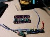
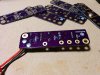
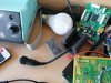
So this is what I've been soldering too. I have it working with a 7" widescreen that came with the set before and am using the faceplate for my controller hookup. I picked a board from RDC mini gcp to actually do the controls.
IMG_20160403_160812.jpg
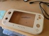
Below is the case I had before by I've made 3dprinted cases so I'll go that route after I scan all the buttons and boards into stl format so I can make a case around that.
IMG_20160403_160833.jpg
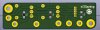
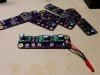
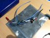
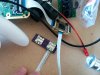
Below is my attempt at the vregs but I thought they were bulky and prone to shorting so I designed a board based off what everyone else is trying out. I just ordered the board so hopefully in 2weeks it should be here. It's my first pcb design so hopefully I did my homework well. Two mounting holes and all surface mounts to get the smallest profile. I have to give credit to the other people especially RDC and downing for those breakout boards. That's what sparked my interest in making this board.
IMG_20160403_160822.jpg 1626b1627a2a81d3700c9b6cc4fcd769.png
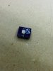
Haven't tried these yet but I got the good display 5.6" displays. Should be better than the 16:9 7" display I've been messing with and then with Badass's gcvid I'll have component. But i will be trying my had at a gcvideo lite .9 soon as well. It will be super difficult for me but hey can't hurt to try.
IMG_20160403_160851.jpg
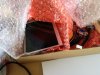
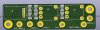
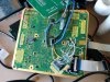
Lastly finally got this working. I made this micro sd wasp replacement board from bentomo. It was a shame that the microsd holders were out on digikey but these were ok for the job. I had to use a heat gun (blow dryer) to flow the solder paste. Gonna say I spent a good time burning the f out of that board but it finally worked. :)
IMG_20160403_160912.jpg

Progress for now. Hoping to trim a board since I finally got a megadrive v6 (been thinking about designing a board like that too if I have time to make it easier to be able to flow solder through vias to solder under the board and not do the drag method) . My posts should be sparatic but I hope to add more to this thread. :)
 

Aurelio

ᕕ( ᐛ )ᕗ
Staff member
.
.
.
.
.
Joined
Mar 3, 2016
Messages
2,229
Likes
2,952
Portables
2
Have you checked if those traces of your regulator breakout board are thick enough? They look too thin in my opinion...
 
Joined
Mar 17, 2016
Messages
39
Likes
5
Have you checked if those traces of your regulator breakout board are thick enough? They look too thin in my opinion...
All of the traces are 50mils (1.27mm). Did I make them too small? If I need to go wider how would you do that with the 08100W? Those contacts are already super small.
 

Aurelio

ᕕ( ᐛ )ᕗ
Staff member
.
.
.
.
.
Joined
Mar 3, 2016
Messages
2,229
Likes
2,952
Portables
2
The GPU need about 3.4A (unless you under power it, but it will still require around 3A). Use this calculator to compute the right thickness. Be conservative and do the calculations using higher currents to be safe (4A atleast).
Oh if you are using OshPark for your boards the thickness of the copper layer is of 1 oz/ft^2 (they were beta testing a new service which provides 2 oz/ft^2 copper layer and thinner pcb, but I don't know if it is still available).
 
Joined
Mar 17, 2016
Messages
39
Likes
5
The GPU need about 3.4A (unless you under power it, but it will still require around 3A). Use this calculator to compute the right thickness. Be conservative and do the calculations using higher currents to be safe (4A atleast).
Oh if you are using OshPark for your boards the thickness of the copper layer is of 1 oz/ft^2 (they were beta testing a new service which provides 2 oz/ft^2 copper layer and thinner pcb, but I don't know if it is still available).
This is what I got. Seems I would need to double the copper to bring that down to 57mil if I wanted to do single traces. I guess to get around it I would have to make lots of different traces converge on the same point to mimic 1 larger trace like run them on the top trace and bottom trace to double the width. That shouldn't be too difficult. And yah they still do the 2oz service. Thanks Aurelio for helping me double check this.
1.JPG
 
Joined
Mar 17, 2016
Messages
39
Likes
5
Alrighty. Version 2 has been ordered both with 1oz and 2oz. The boards were cheap enough that I figured why not. I bumped all the traces to 60mils and doubled the lines on the back side. I could have done V1 with 2oz after fixing the traces I'll get to do some testing. I'll probably need another set of vregs now. See renders below. I realize that some places created a loop so hopefully I haven't created too much mag interference.
3.JPG 4.JPG
 
Joined
Mar 17, 2016
Messages
39
Likes
5
Got my thinner copper thickness with double traces back and started to populate the board. Starting to look good. Won't know till the weekend. Waiting on resistors and capacitors to finish it off.IMG_20160414_211858.jpg
 

cheese

the tallest memer in town
Staff member
.
.
.
Joined
Mar 2, 2016
Messages
2,759
Likes
2,431
Location
Florida
That looks great, really professional! Are the larger vias connected to ground, or are they just mounting holes? It looks like they're not connected in the render, but I'm not sure...
 
Joined
Mar 17, 2016
Messages
39
Likes
5
That looks great, really professional! Are the larger vias connected to ground, or are they just mounting holes? It looks like they're not connected in the render, but I'm not sure...
Thanks cheese for the compliment. Kicad said they were mounting holes. I guess they're just big vias. They aren't connected to any plane or other traces.
 
Joined
Mar 17, 2016
Messages
39
Likes
5
Success for V2 and my first ever PCB. It outputs 1.9 , 3.3, and 5v. I will test it next off of my test bed. I think I can get this smaller but the catch will be no mounting holes and it will need the 2oz copper. Also the solder holes can be pads or square pads. I can make it so it needs a bracket around the edges to fit. Hardest part about soldering this is removing the pins it already has. Might try some tricks with that. If anyone wants one I can make the file public.IMG_20160415_222207.jpg IMG_20160415_222157.jpg
 
Joined
Mar 17, 2016
Messages
39
Likes
5
So now that I have a little bit more time before exams I decided to design one more iteration of the power board before I really start the portable designing. The whole idea is that one of the regs the PTR08100W is optional and that it can be soldered in without taking out the right hand headers. It'll need some tape (normal or liquid) if it touches other stuff but ya'll know that already..... So here's the design. I'm doing it in 2oz since I have single traces 70mil wide for everything. Second PCB and I think I did something badish with the extra pads for 3.3, 1.9 and 5V, still learning. Also hoping the Vias work. If not I'll just jumper wire a line around the side.
upload_2016-5-3_23-1-19.png
 
Joined
May 1, 2016
Messages
53
Likes
20
Are you going to make that board public on OshPark and or release the eagle files? It's a beautiful update to Zenloc's regulator. Also do you have to reflow each surface mount component or can you solder them on by hand.
 

ShockSlayer

the real
.
.
Joined
Jan 16, 2016
Messages
1,512
Likes
3,940
Location
standing up
Portables
please do not ask!!!! I will NOT respond
Just so you know, only one of those is called zenloc's regs; the PTH08080's been around since the benheck days. :P
 
Joined
Mar 17, 2016
Messages
39
Likes
5
Yah shockslayer is right, though I appreciate the compliment Trevor :). These be the Sl33py's regs.....argh.

Trevor I'll definitely post the files on oshpark but first I need to test them for temperature and if I can get enough current through the vias. It's the second board I've designed so I'm still pretty green to all of this especially with vias. So it might be a couple of weeks before I give the ok, since I just ordered the boards.

You can reflow the bottom to get most of it on and then hand solder the vregs normally and then touch the 5V out cap if you need to at the end or you can do them all by hand. If my thinking is correct C1 to C2 and C5 to C4 is going to be hard hand soldering but since they both sit on the same gnd line it won't matter if you bridge the pairs. Please correct me if I'm wrong.
 
Joined
May 1, 2016
Messages
53
Likes
20
It's official, this is Sl33py's reg. That sounds right it would be hard to get the heat through the board hand soldering.
 
Joined
Mar 17, 2016
Messages
39
Likes
5
Excited got moopers low battery light to work. Next onto the gcvideo lite. Got the main parts soldered.IMG_20160507_135710.jpg
 
Joined
Mar 17, 2016
Messages
39
Likes
5
Well I hit a snag. I was going through modifying my heatsink add arctic silver to it and bam nothing turned on. Thought my vregs went out. One of them was buzzing, the 3.3V one. So like anyone would do, I tore everything up and started over. The last thing I did was take off the heatsink and guess what it turned on.....so wtf.

I'll probably add a separate topic to this but does anybody know why solder paste would cause a short? There isn't any over spill onto the board so I don't see why there would be shorting. I think i'm going to buy some thermal pads and see if that doesn't help. Would be nice if this didn't happen, really want to start on case design, going retro with it.
 

cheese

the tallest memer in town
Staff member
.
.
.
Joined
Mar 2, 2016
Messages
2,759
Likes
2,431
Location
Florida
The thermal pads might have some cushion to them to prevent having too much pressure on the processor, or the particular paste you have may be slightly conductive?
 
Top