Solved Odd screen issue

ScrambledFrequency

Custom title wanter
.
Joined
Sep 12, 2020
Messages
137
Likes
30
Location
The Void
Portables
1
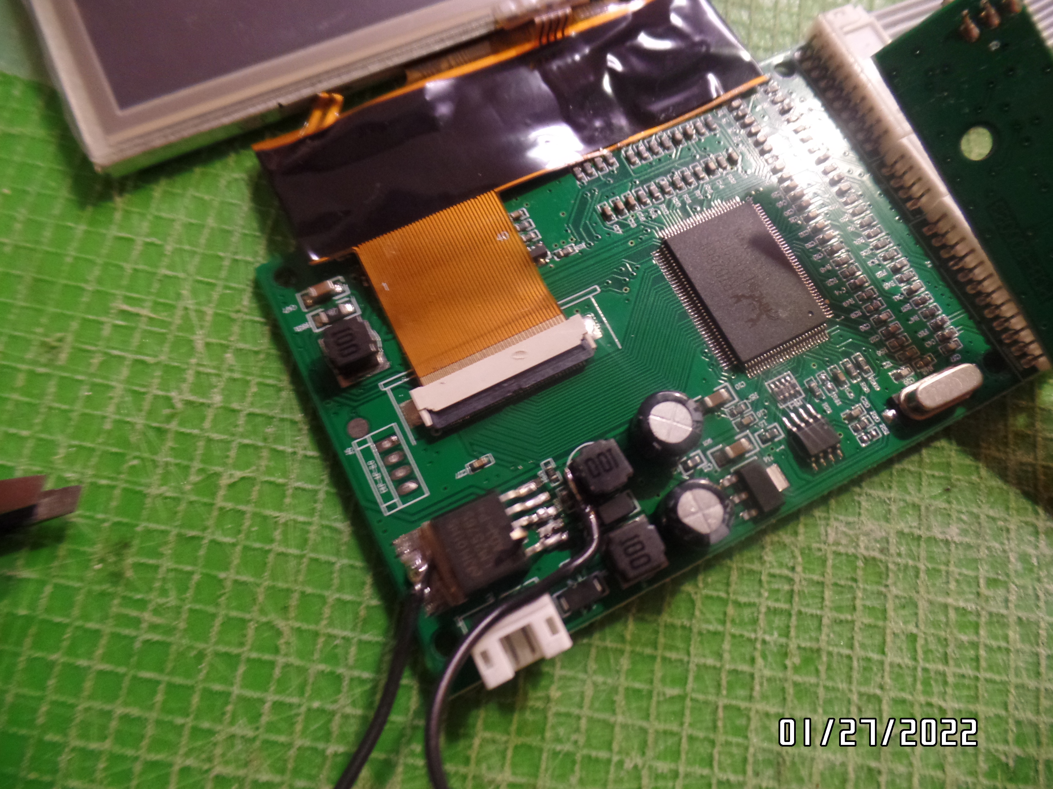
I have been working on wiring up a screen for testing.
I did the 3.3v mod posted on 4layer's site.
Nothing is short circuited.
The screen's power light comes on and then goes out when I press the power button.
I am powering it off an RVL-PMS2.
SAM_1681.JPG
 

Gman

RTFDS
Staff member
.
.
.
.
.
Joined
Feb 25, 2016
Messages
1,437
Likes
2,887
Do you have an input video signal connected?
 

ScrambledFrequency

Custom title wanter
.
Joined
Sep 12, 2020
Messages
137
Likes
30
Location
The Void
Portables
1
No, but it should give me a blue screen with the input type, right?
 

Gman

RTFDS
Staff member
.
.
.
.
.
Joined
Feb 25, 2016
Messages
1,437
Likes
2,887
normally it will be blue screen for a few seconds and then turn black.
 

ScrambledFrequency

Custom title wanter
.
Joined
Sep 12, 2020
Messages
137
Likes
30
Location
The Void
Portables
1
Yep that's what I meant.
It's not even giving me that.
What could it be?
Too much power draw?
Unconfigured PMS?
ALIENS?!(just kidding)
 

Gman

RTFDS
Staff member
.
.
.
.
.
Joined
Feb 25, 2016
Messages
1,437
Likes
2,887
I dont know. why dont you try it with a video signal
 

ScrambledFrequency

Custom title wanter
.
Joined
Sep 12, 2020
Messages
137
Likes
30
Location
The Void
Portables
1
OK, I got the screen up and running, but now the wii does not seem to be outputting a video signal.
SAM_1684.JPG

SAM_1685.JPG

SAM_1687.JPG

The wii is getting hot, so it probably is working.
 

Gman

RTFDS
Staff member
.
.
.
.
.
Joined
Feb 25, 2016
Messages
1,437
Likes
2,887
you've soldered the video in the wrong spot. all your video wires are connected to nothing on the wii. Also the wiring does not look very good.
 

ScrambledFrequency

Custom title wanter
.
Joined
Sep 12, 2020
Messages
137
Likes
30
Location
The Void
Portables
1
What is the right spot for video?
I soldered the wire from the white wire on the screen to the wire right above the BGR you see on the wii.
 

Gman

RTFDS
Staff member
.
.
.
.
.
Joined
Feb 25, 2016
Messages
1,437
Likes
2,887
if you removed the capacitors like you have done you need to solder on the input side which is the opposite to where you have connected
 

ScrambledFrequency

Custom title wanter
.
Joined
Sep 12, 2020
Messages
137
Likes
30
Location
The Void
Portables
1
I resoldered to the input side like you said, but it still is not working.
The screen refused to accept any inputs after I soldered the wii's input, so maybe it's the screen.
The wii is not miswired unless my H and V sync wires crisscrossed.(I'm going to patch in VGA, but am using composite for testing.)
The screen still turns on (blue screen) but no inputs register.
Did I bust my screen ALREADY??
 

Gman

RTFDS
Staff member
.
.
.
.
.
Joined
Feb 25, 2016
Messages
1,437
Likes
2,887
It's more likely your wii is not turning on. You need to eliminate a variable by testing the wii on your tv.
 

ScrambledFrequency

Custom title wanter
.
Joined
Sep 12, 2020
Messages
137
Likes
30
Location
The Void
Portables
1
OK, I thought I should probably do that.
My wii is heating up, though.
Would it be broken if it's not turning on?
 
Last edited:

ScrambledFrequency

Custom title wanter
.
Joined
Sep 12, 2020
Messages
137
Likes
30
Location
The Void
Portables
1
OK, my wii is not outputting a signal.
However, all the voltages are connected, and I checked the resistances.
Anything I'm doing wrong?
 

Gman

RTFDS
Staff member
.
.
.
.
.
Joined
Feb 25, 2016
Messages
1,437
Likes
2,887
OK, my wii is not outputting a signal.
However, all the voltages are connected, and I checked the resistances.
Anything I'm doing wrong?
you are absolutely doing something wrong. What it is, I dont know. You need to do more troubleshooting. I already told you the wiring is not perfect.
 

Stitches

2 and a Half Dollarydoos
Staff member
.
.
Joined
Feb 5, 2017
Messages
3,848
Likes
3,025
Location
Banana Bender Land, Australia
Portables
6
Can you show us your U10 via wiring on the other side of the board?
 
Joined
Jul 9, 2020
Messages
227
Likes
498
Its difficult to see from the blurry photos... But i think you are adding extra voltage wires to your u10 relocation that are not necessary. The u5 pads already provide ground and 3v3 to the chip. Did you remember to cut the trace that leads to the output pin? I agree with where @Stitches was going with u10 questions.

Check the output pin of the u10 relocation. Is it metering 3v3? Check the u10 gpu via, Is it also metering 3v3? If this voltage is not present, wii will not complete its boot cycle. But the chipset will still get hot... so warm chips are not enough to tell that the wii is functioning yet.

Try to take some less blurry photos of the front and back of your wired trim. Share them here, and we will all figure it out together. :)
 

ScrambledFrequency

Custom title wanter
.
Joined
Sep 12, 2020
Messages
137
Likes
30
Location
The Void
Portables
1
I did the U10 wiring awhile ago, and even opened a thread on it.
The extra voltage wires are because I accidentally scratched off the trace too far.
I eventually got it working but now it stopped working.
Here's a photo
SAM_1447.JPG

EDIT: I am getting a fuzzy and distorted image on a regular tv, but my screen is not getting anything.
Do I need to use a heavier wire( interference and all that)?
Or is it a problem with the screen?
 
Last edited:

Gman

RTFDS
Staff member
.
.
.
.
.
Joined
Feb 25, 2016
Messages
1,437
Likes
2,887
if the wii looks like your profile pic than I am not convinced its the screen
 

ScrambledFrequency

Custom title wanter
.
Joined
Sep 12, 2020
Messages
137
Likes
30
Location
The Void
Portables
1
Yep haha.
I'm thinking there's a crap ton of interference, so I'll try a heavier wire.
 
Top