
- Joined
- Jul 9, 2020
- Messages
- 230
- Likes
- 500
Hey Yall... I've been working on an interesting project the last few weeks. Thought it would be fun to show off...was gonna post in cutting edge but its not quite done with. Still wanted to share progress.
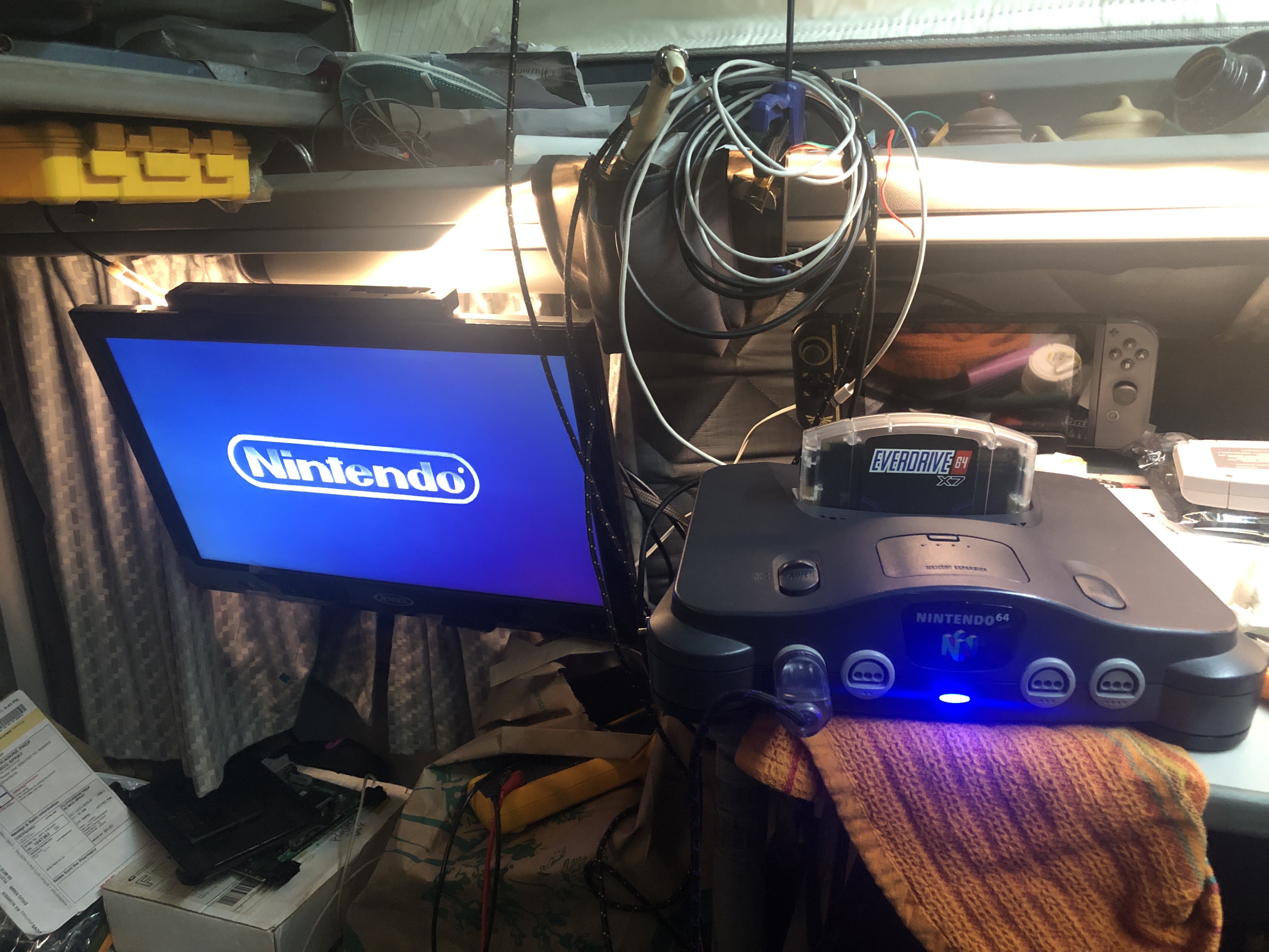
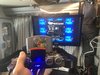
It may look like a regular n64 but beneath its stock shell is so much more.
Features:
- N64 Digital HDMI Mod with analog RGB amp running parallel (both hdmi and rgb are part of pixel's board)
- 1x, 1.5x, 2x, and 3x OverClock modes.
- Added heatsinks with active cooling (fan has an on off switch for quiet convenience)
- Region Free Cartridge slot
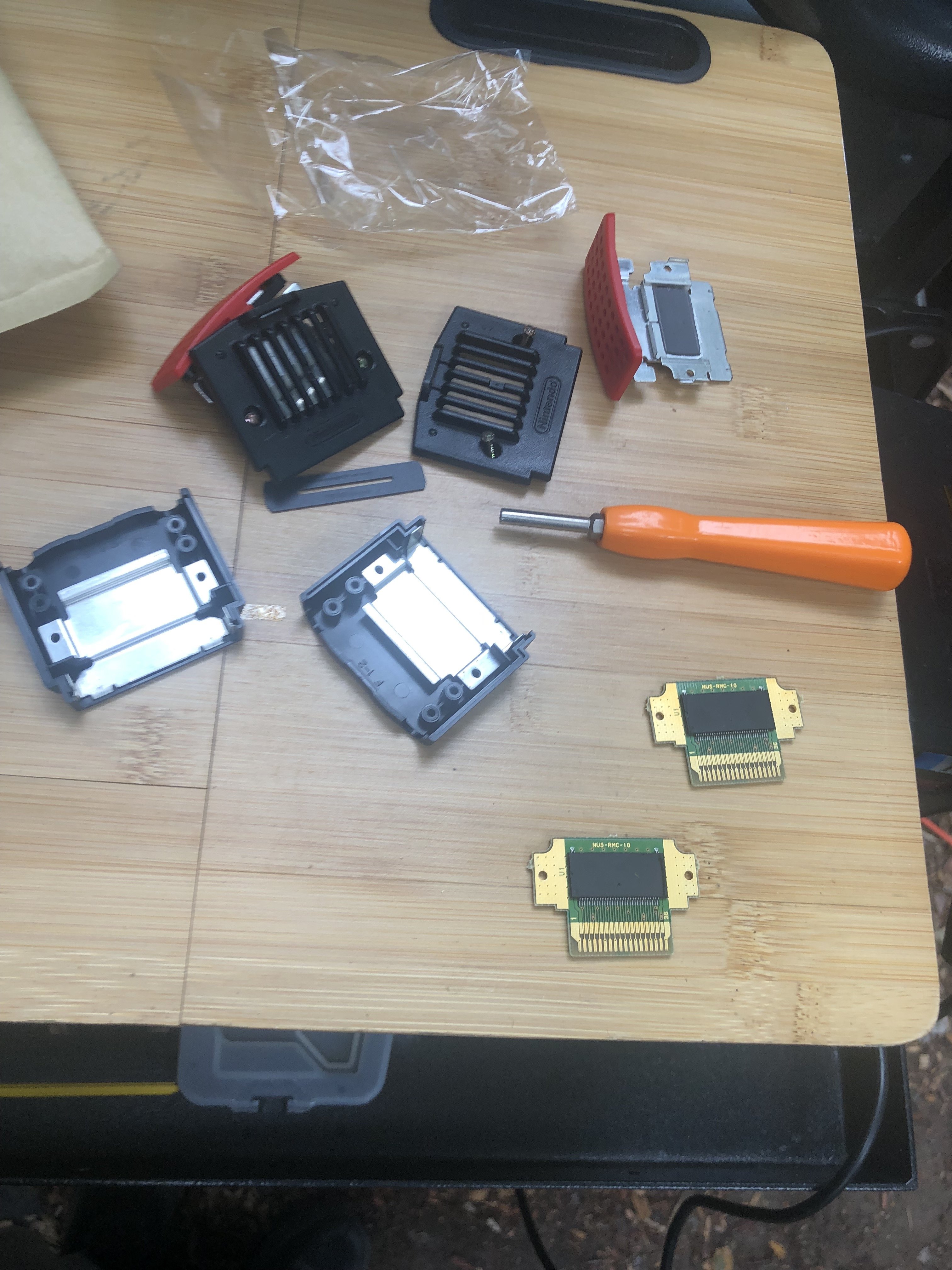
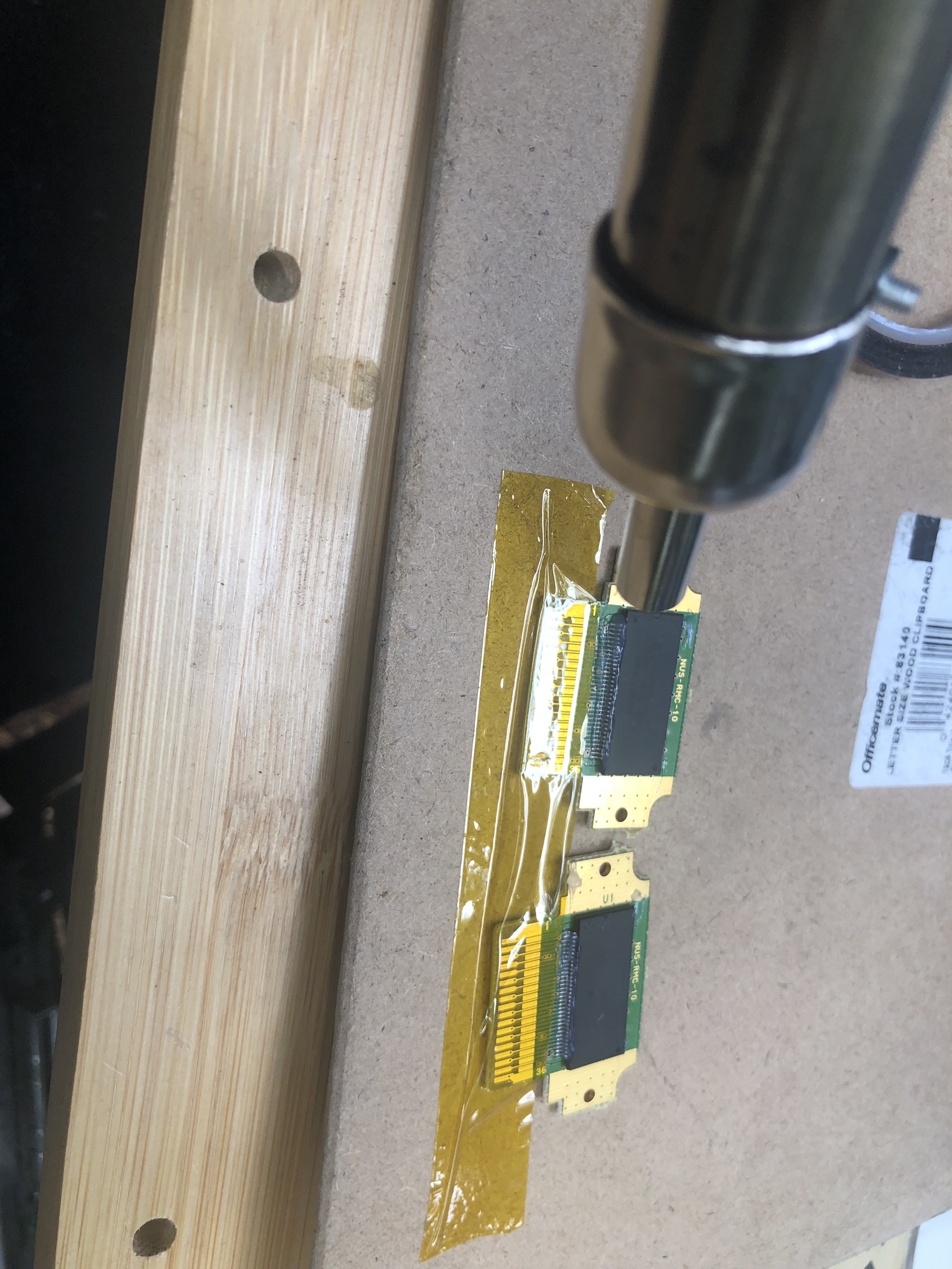
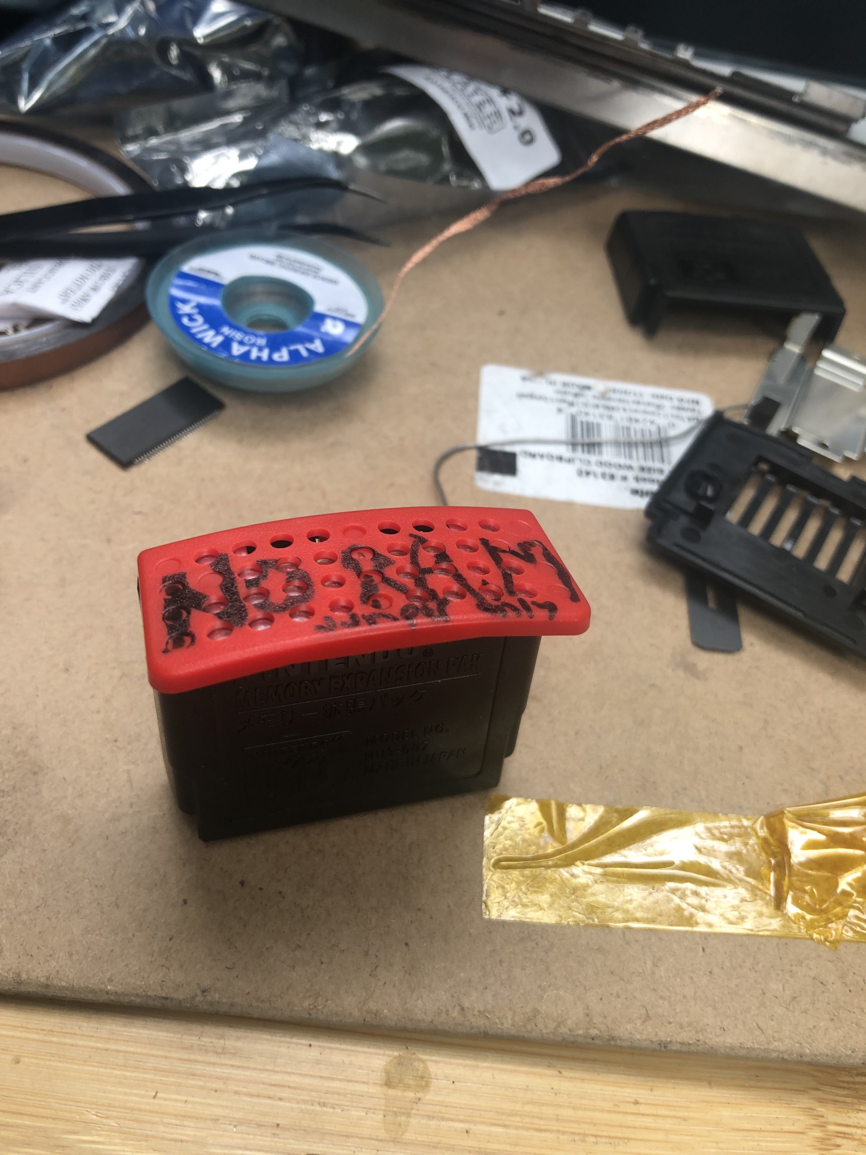
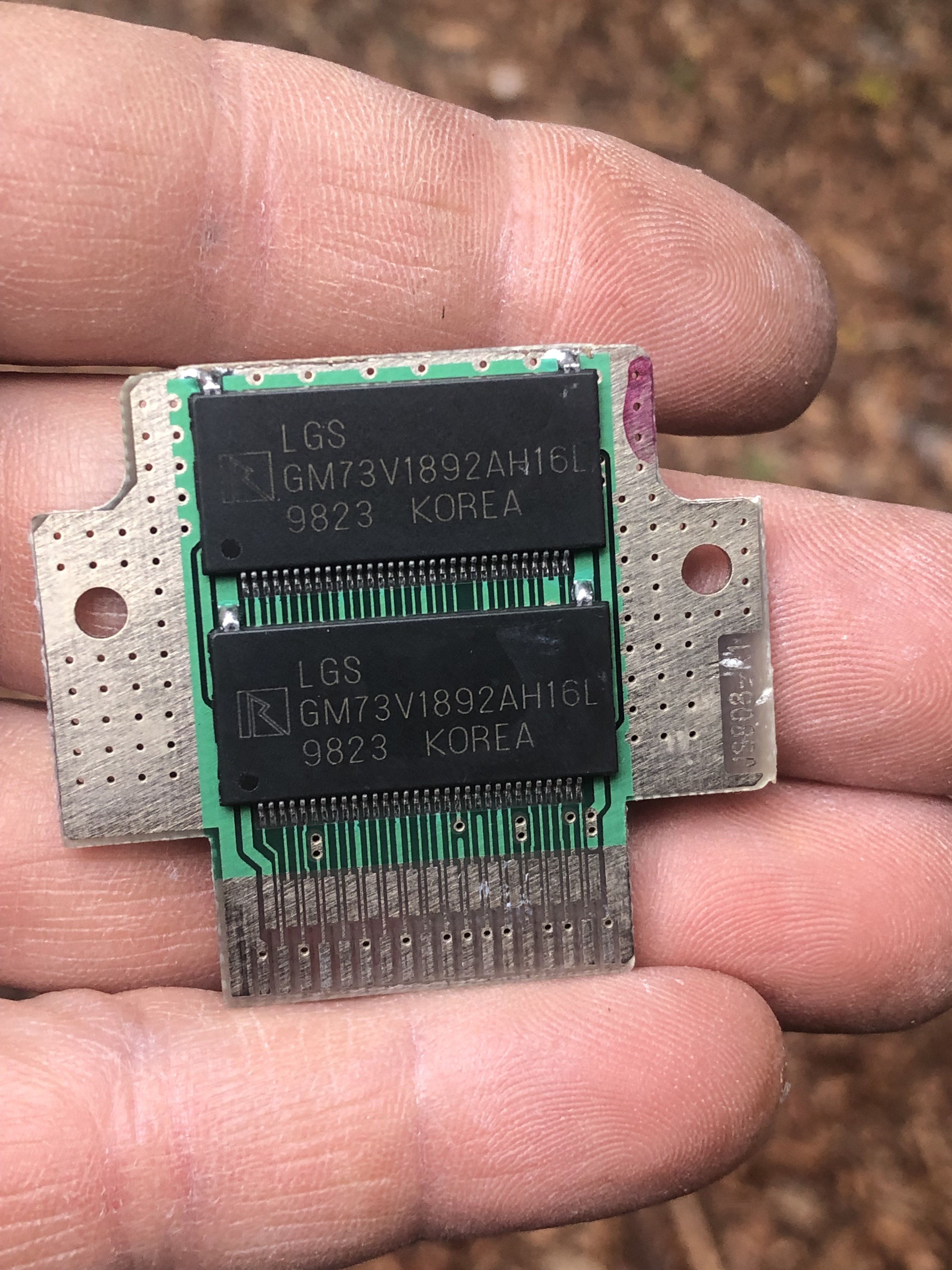
- Internal Expansion pak -- 8mb on the board. RamSwapped 2x 2mb chips for 2x4mb (harvested from expansion paks)
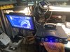
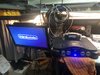
- And most importantly, the blue LED swap mod.
So the project is for a client who wanted to have a platform to develop on the n64. He wanted all the possible available ram and overclocks too. I offered to also do the pixel fx hdmi mod as the kicker!
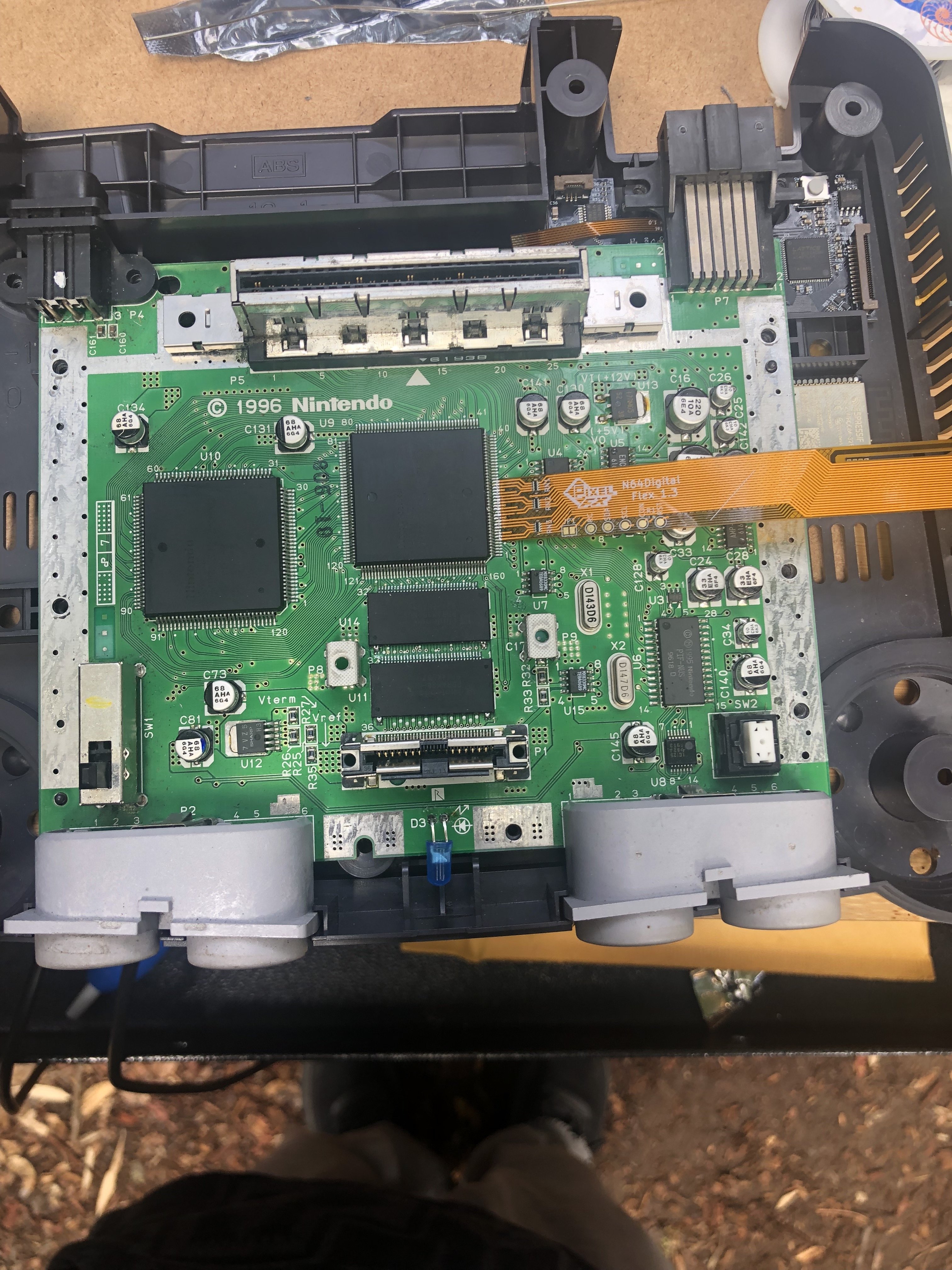
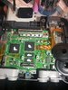
The board got a whole refurbish with recap and deep clean... start from a good base.
Took my time to remove the ram from the expansion paks and put one back in the expansion pak case to use as the jumper pak for now. Eventually will use RamExpander third party pak with two more swapped 4mb chips on there.

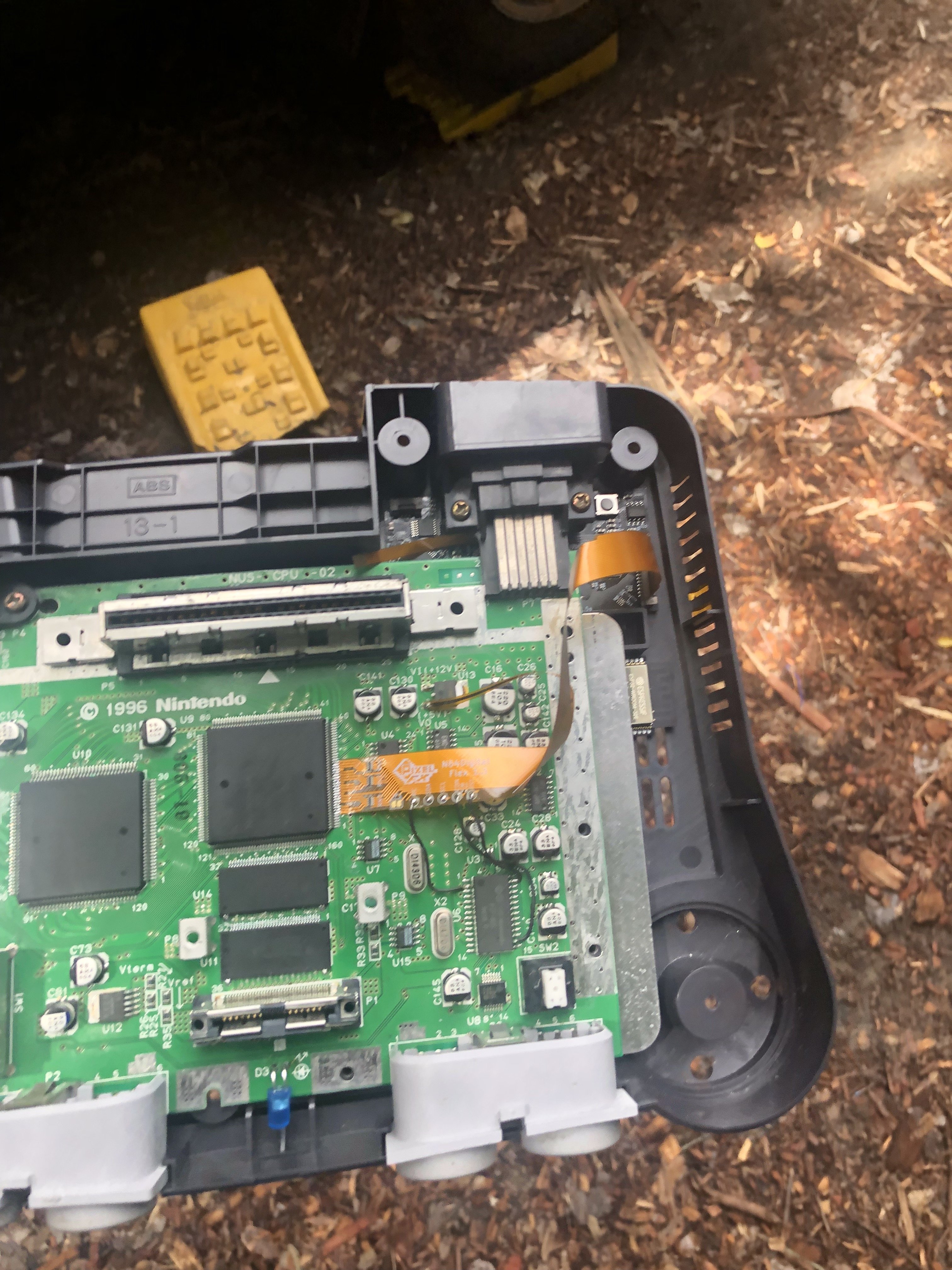
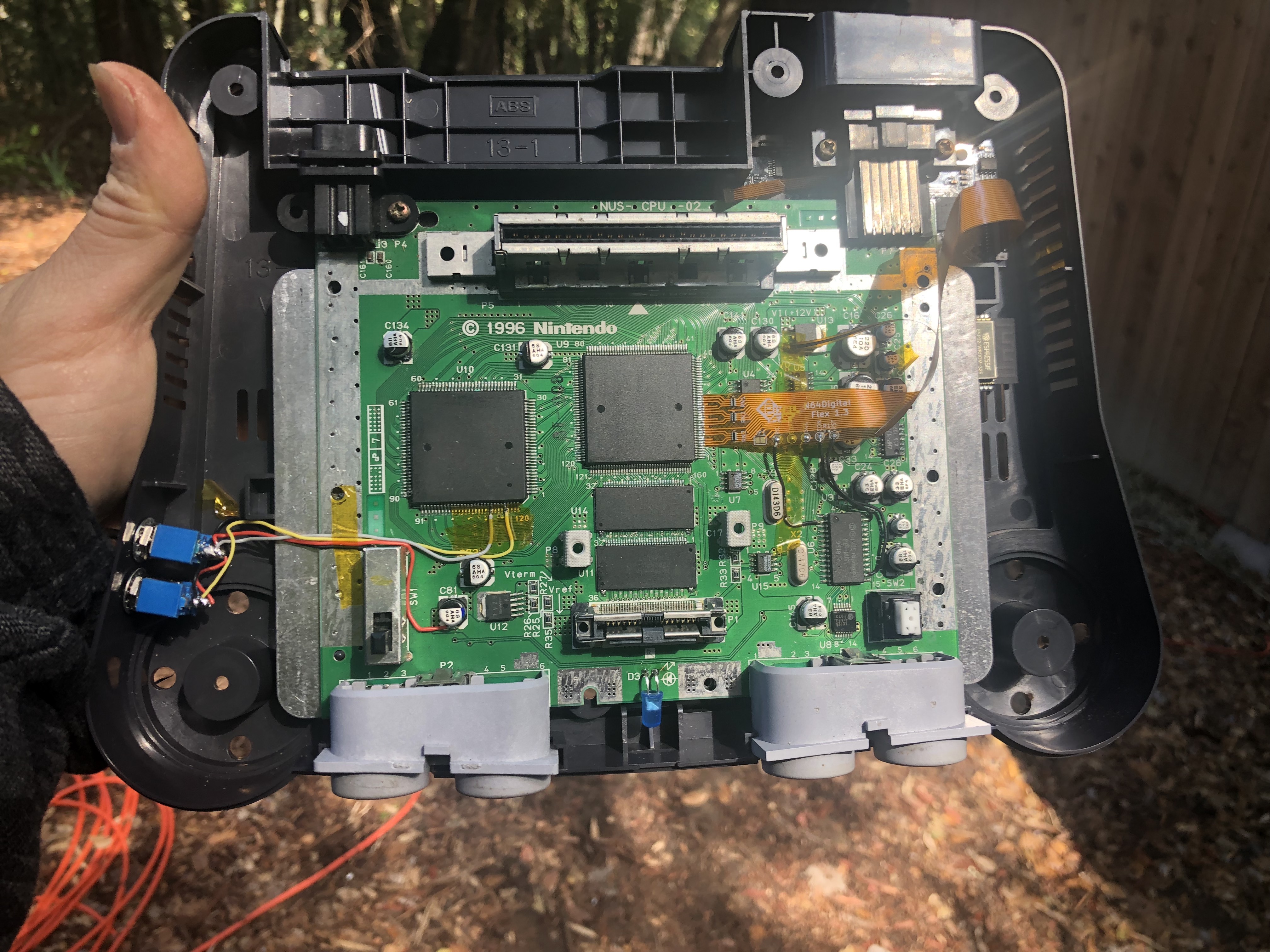
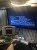
Next was the HDMI mod:
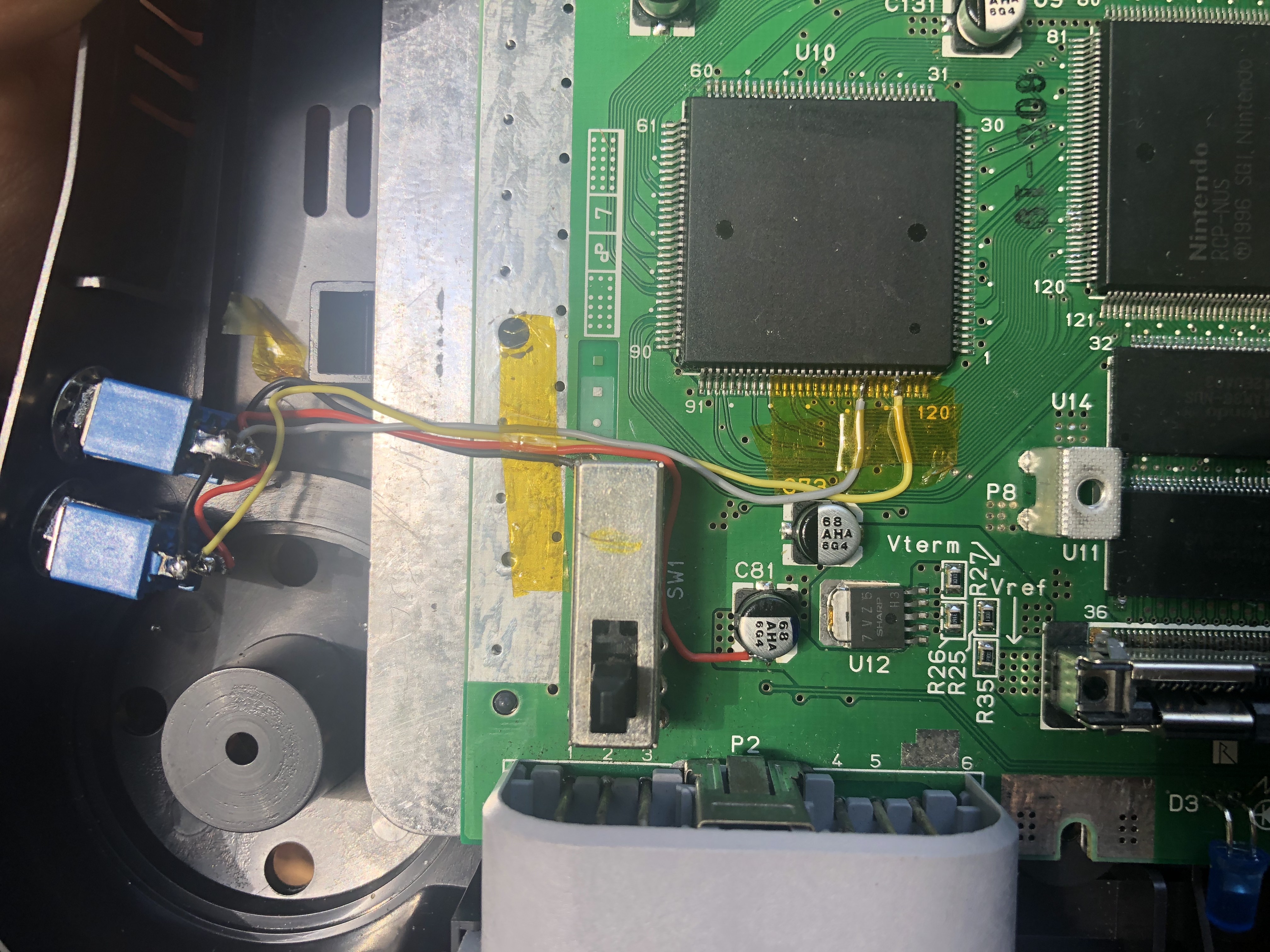
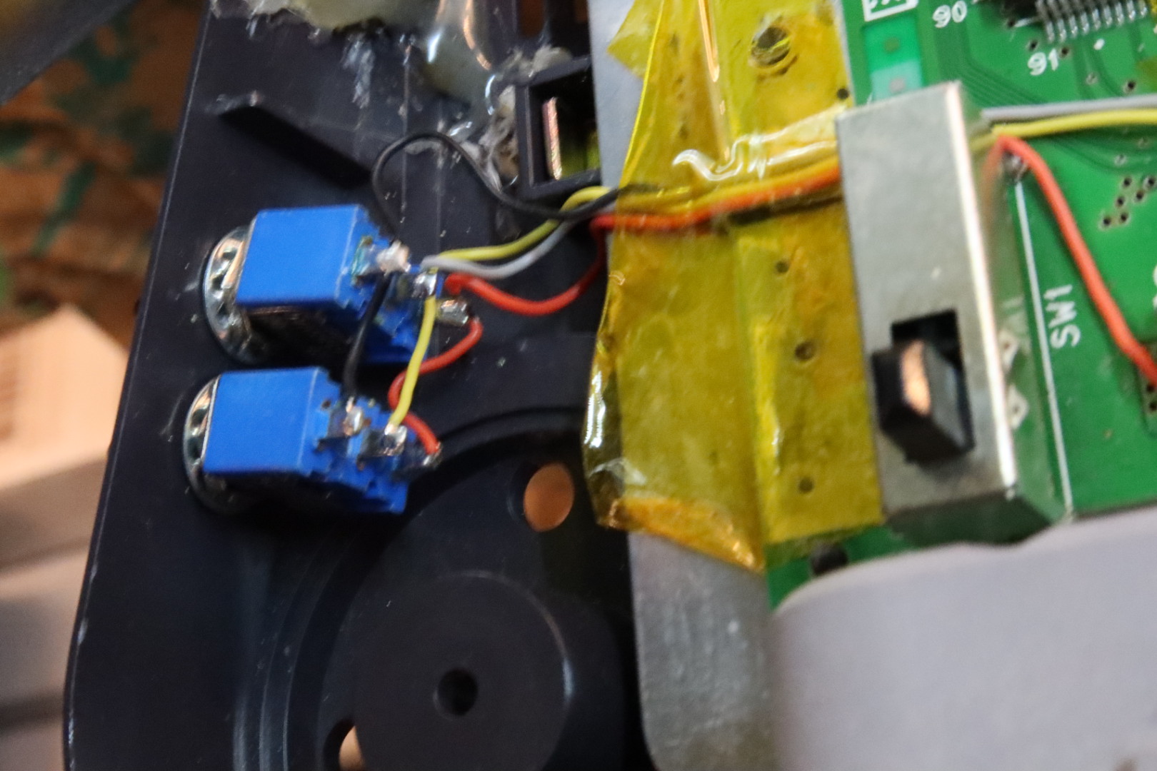
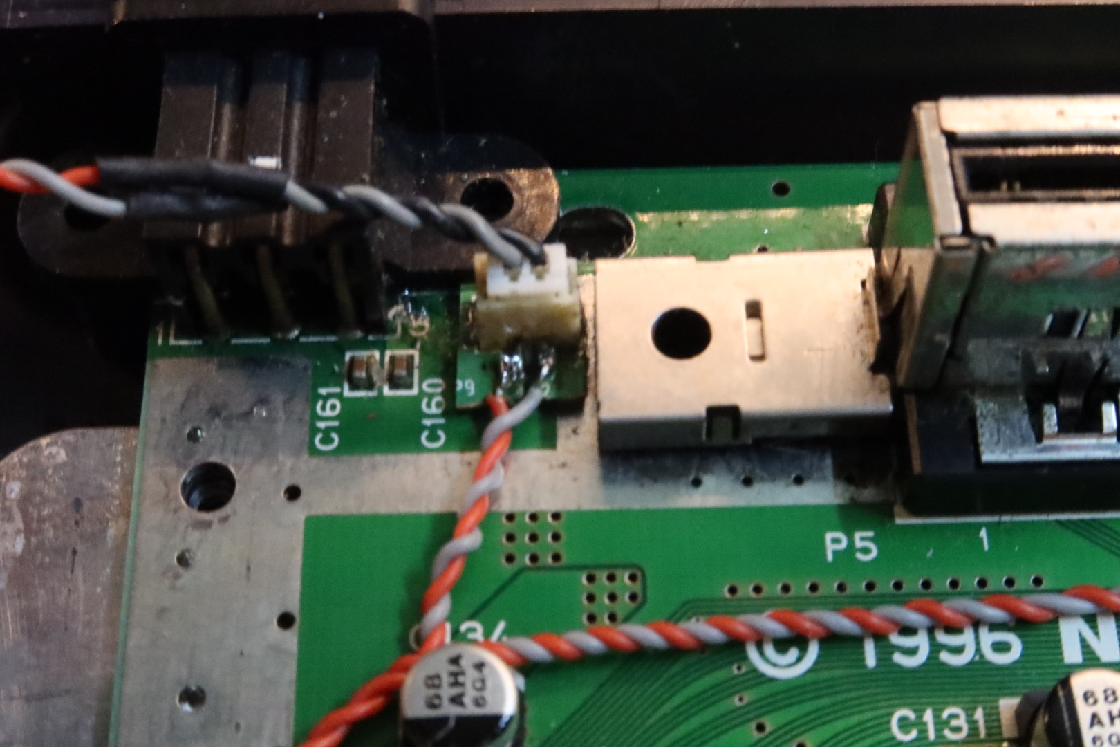
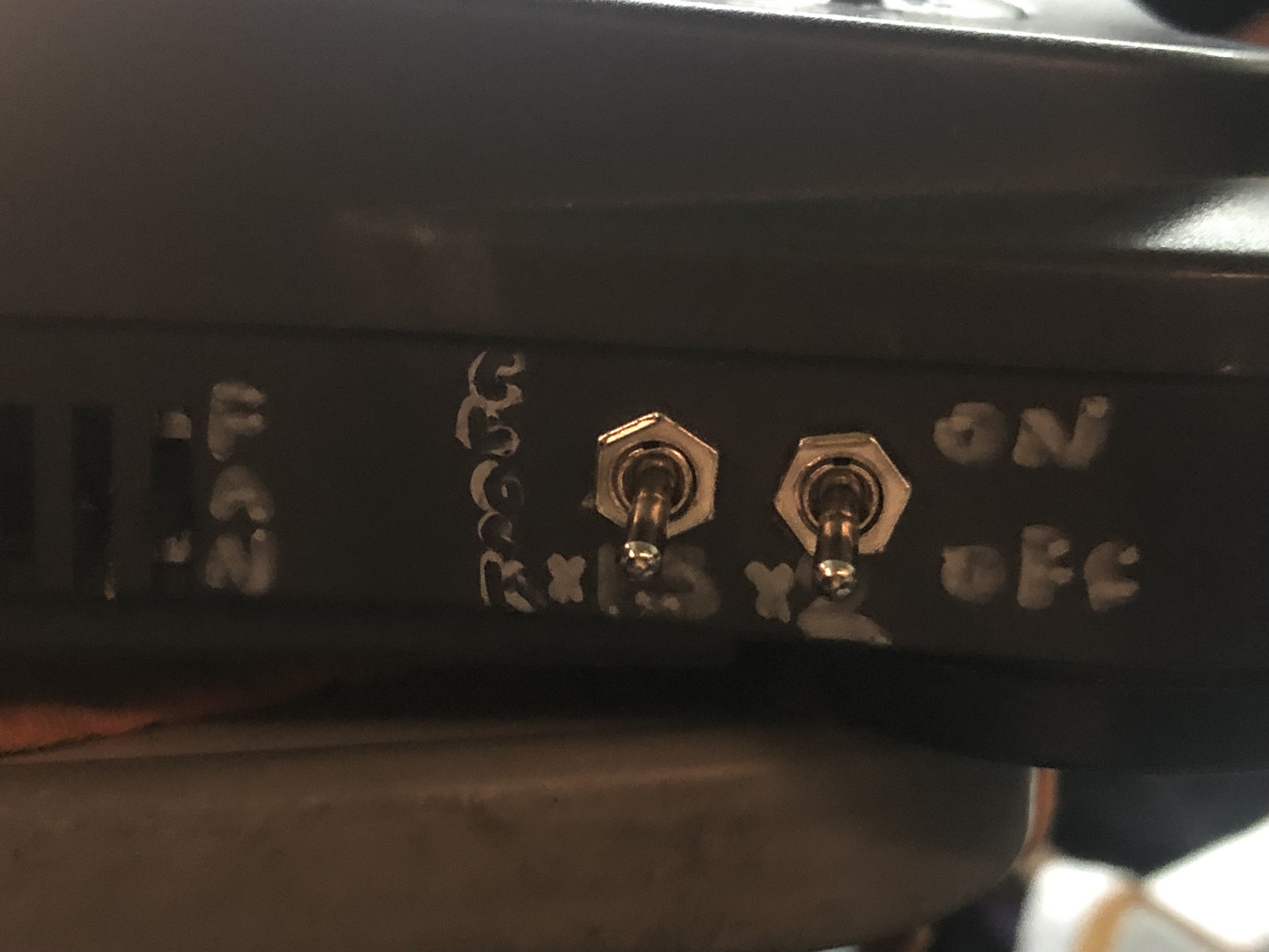
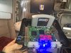
Next Overclock mod. Its pretty simple actually. CPU Pin 112 and 116 get lifted. If each pin is connected to ground then the console runs at stock clock speed, aka 1x. If 112 is pulled high to 3v3, while 116 stays low, the unit runs at 1.5x clock speed. If 112 is pulled low to GND, while 116 gets pulled to 3v3, the unit runs at 2x clock speed. (both switches up is 1.5x X 2x = 3x but this speed crashes the n64 every time so its useless). Each cpu pin is attached to the center pin of a DPST, with the lower pins wired to 3v3 and the upper pins wired to ground. (when switch is up it connects the center and bottom pin, when switch is down it connects the center and upper pins). Pulled ground and 3v3 from the motherboard. Made sure that i had a good layer of kapton riding up behind the lifted pins so there were no potential shorts. Then some kapton over the wires to make sure there is stress relief should they be tugged for some reason. e viola. Overclock mod.
Oh yes, i also trimmed out a thin channel in the cover plate where the wires would pass so there will be no pinch shorting in the future. (unfortunately i dont have a photo of that)
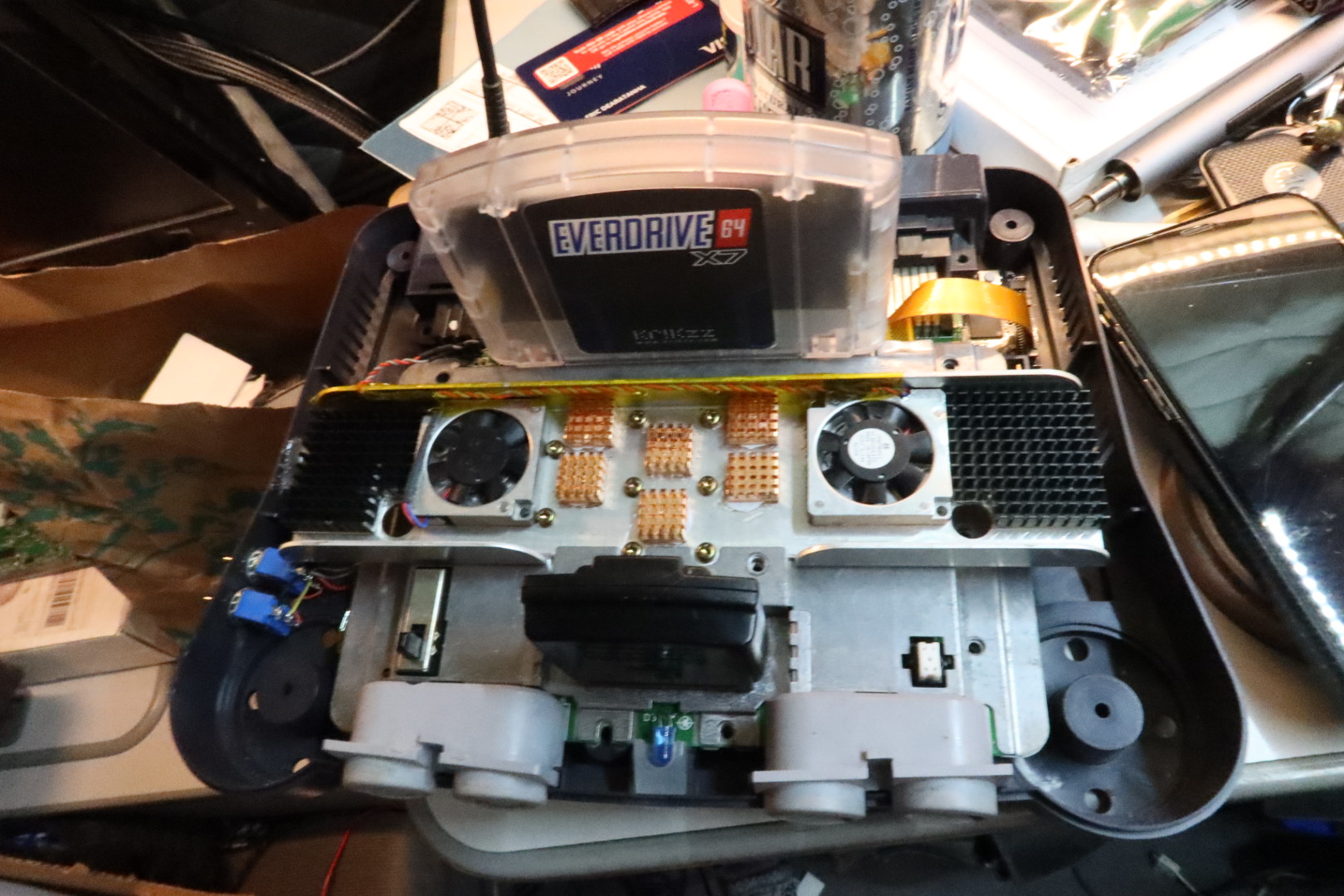
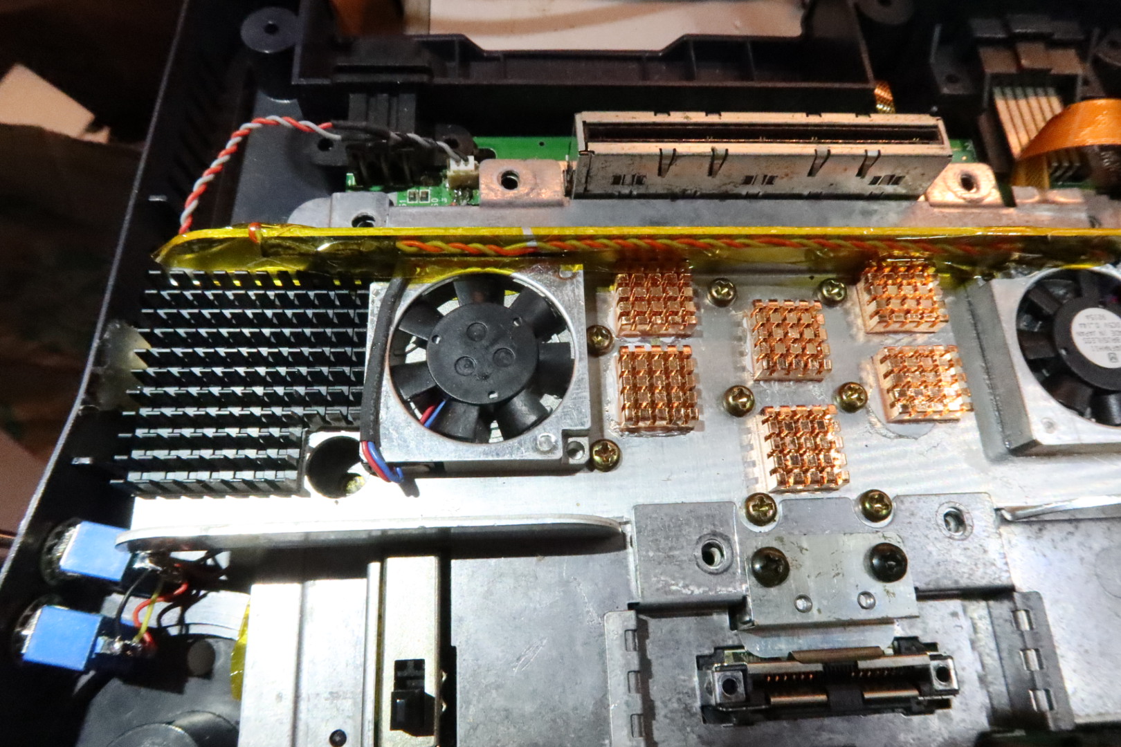
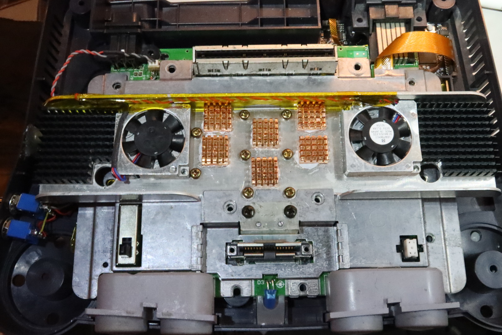
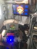
Overclocking leads to more heat. My client wants this to last forever so we had to add active cooling ... decided to put fan switch for quietness and also a header on the 5v so I could do maintenance easily in the future. Added copper heatsinks to center part of stock aluminum heatsink and added two more heatsinks with two blower fans on the wings. I had to trim corners off the black heat sink to retain access to the mounting screws. I also removed two of the screws on the far left as they interfered with the fan placement. They were just for holding the upper heatsink wing down to the bottom plate... but there are 8 others doing that job so its fine. The fans used are actually the same ones used in the Gwii -- top sucker, side blower x2.Everything is glued down with a dab of super glue in the corners and a dab of arctic silver thermal paste in the center. Wires routed cleanly and ganged together at the header. The switch on the side is just breaking the 3v3 to the fans.
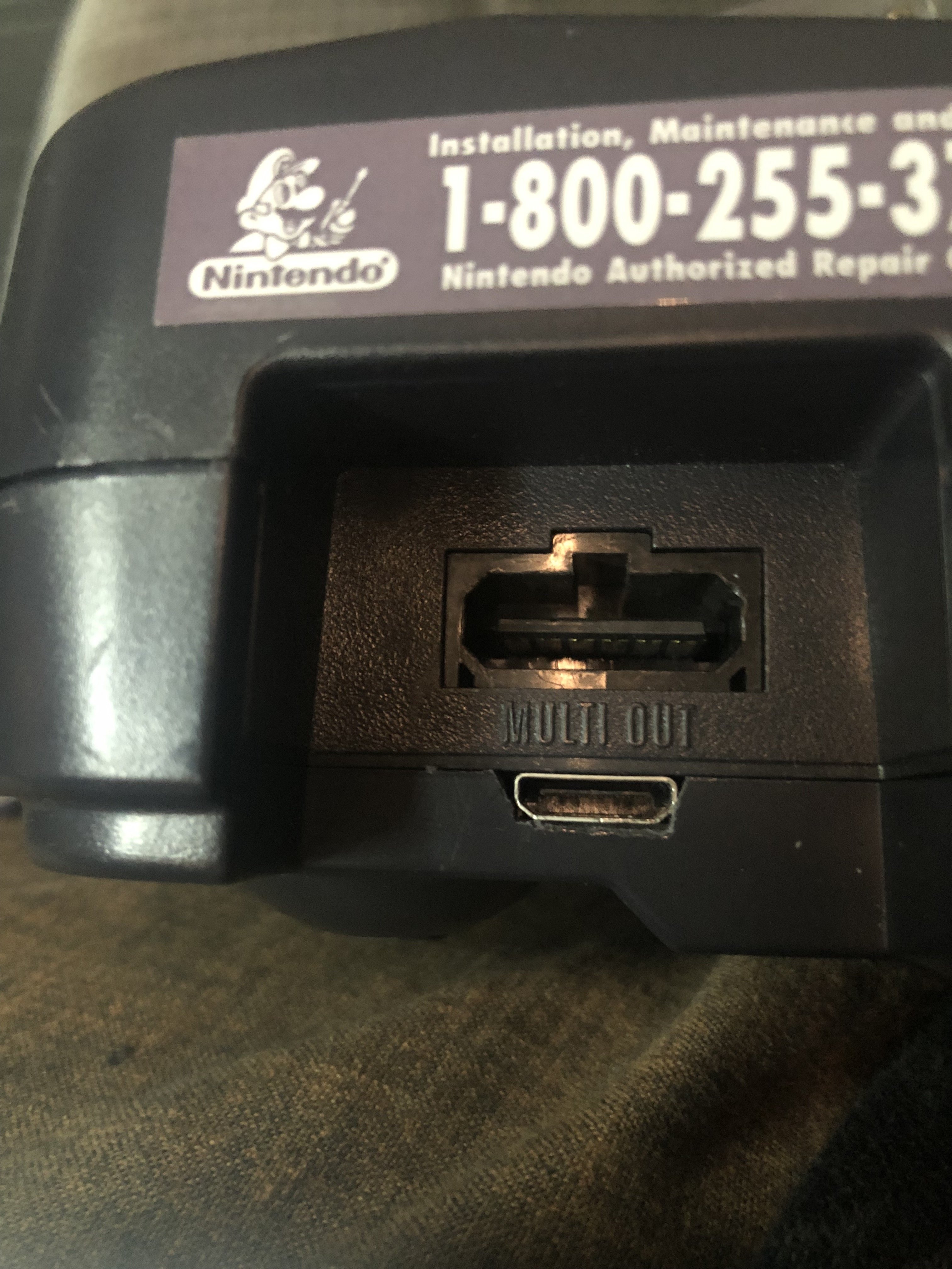
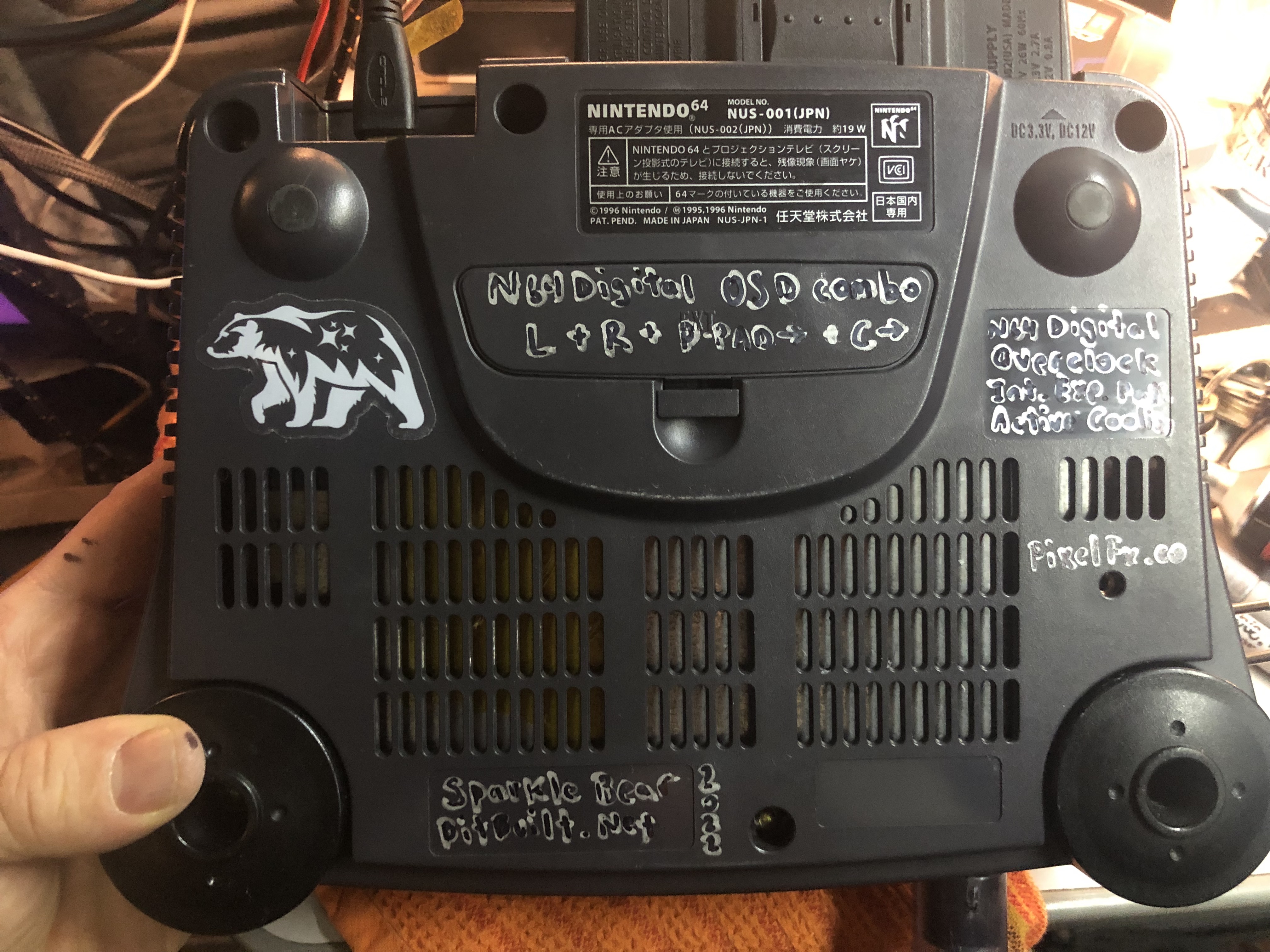
At the end I just added a personal touch to the bottom of the case, offering info about the mods and the key combo for n64digital OSD control.
What a fun mod project... All there is left is to source two more expansion paks and ramswap the
It may look like a regular n64 but beneath its stock shell is so much more.
Features:
- N64 Digital HDMI Mod with analog RGB amp running parallel (both hdmi and rgb are part of pixel's board)
- 1x, 1.5x, 2x, and 3x OverClock modes.
- Added heatsinks with active cooling (fan has an on off switch for quiet convenience)
- Region Free Cartridge slot
- Internal Expansion pak -- 8mb on the board. RamSwapped 2x 2mb chips for 2x4mb (harvested from expansion paks)
- And most importantly, the blue LED swap mod.
So the project is for a client who wanted to have a platform to develop on the n64. He wanted all the possible available ram and overclocks too. I offered to also do the pixel fx hdmi mod as the kicker!
The board got a whole refurbish with recap and deep clean... start from a good base.
Took my time to remove the ram from the expansion paks and put one back in the expansion pak case to use as the jumper pak for now. Eventually will use RamExpander third party pak with two more swapped 4mb chips on there.
Next was the HDMI mod:
Next Overclock mod. Its pretty simple actually. CPU Pin 112 and 116 get lifted. If each pin is connected to ground then the console runs at stock clock speed, aka 1x. If 112 is pulled high to 3v3, while 116 stays low, the unit runs at 1.5x clock speed. If 112 is pulled low to GND, while 116 gets pulled to 3v3, the unit runs at 2x clock speed. (both switches up is 1.5x X 2x = 3x but this speed crashes the n64 every time so its useless). Each cpu pin is attached to the center pin of a DPST, with the lower pins wired to 3v3 and the upper pins wired to ground. (when switch is up it connects the center and bottom pin, when switch is down it connects the center and upper pins). Pulled ground and 3v3 from the motherboard. Made sure that i had a good layer of kapton riding up behind the lifted pins so there were no potential shorts. Then some kapton over the wires to make sure there is stress relief should they be tugged for some reason. e viola. Overclock mod.
Oh yes, i also trimmed out a thin channel in the cover plate where the wires would pass so there will be no pinch shorting in the future. (unfortunately i dont have a photo of that)
Overclocking leads to more heat. My client wants this to last forever so we had to add active cooling ... decided to put fan switch for quietness and also a header on the 5v so I could do maintenance easily in the future. Added copper heatsinks to center part of stock aluminum heatsink and added two more heatsinks with two blower fans on the wings. I had to trim corners off the black heat sink to retain access to the mounting screws. I also removed two of the screws on the far left as they interfered with the fan placement. They were just for holding the upper heatsink wing down to the bottom plate... but there are 8 others doing that job so its fine. The fans used are actually the same ones used in the Gwii -- top sucker, side blower x2.Everything is glued down with a dab of super glue in the corners and a dab of arctic silver thermal paste in the center. Wires routed cleanly and ganged together at the header. The switch on the side is just breaking the 3v3 to the fans.
At the end I just added a personal touch to the bottom of the case, offering info about the mods and the key combo for n64digital OSD control.
What a fun mod project... All there is left is to source two more expansion paks and ramswap the
Attachments
-
 465.9 KB Views: 281
 -
 1.8 MB Views: 242
 -
 2.1 MB Views: 240
 -
 1.8 MB Views: 263
 -
 1.6 MB Views: 239
 -
 2.4 MB Views: 246
 -
 2.2 MB Views: 310
 -
 2.1 MB Views: 286
 -
 2.2 MB Views: 267
 -
 2.1 MB Views: 219