Worklog Louii road

Jpin

.
Joined
Sep 17, 2021
Messages
39
Likes
24
Hi guys here is an update of my work.

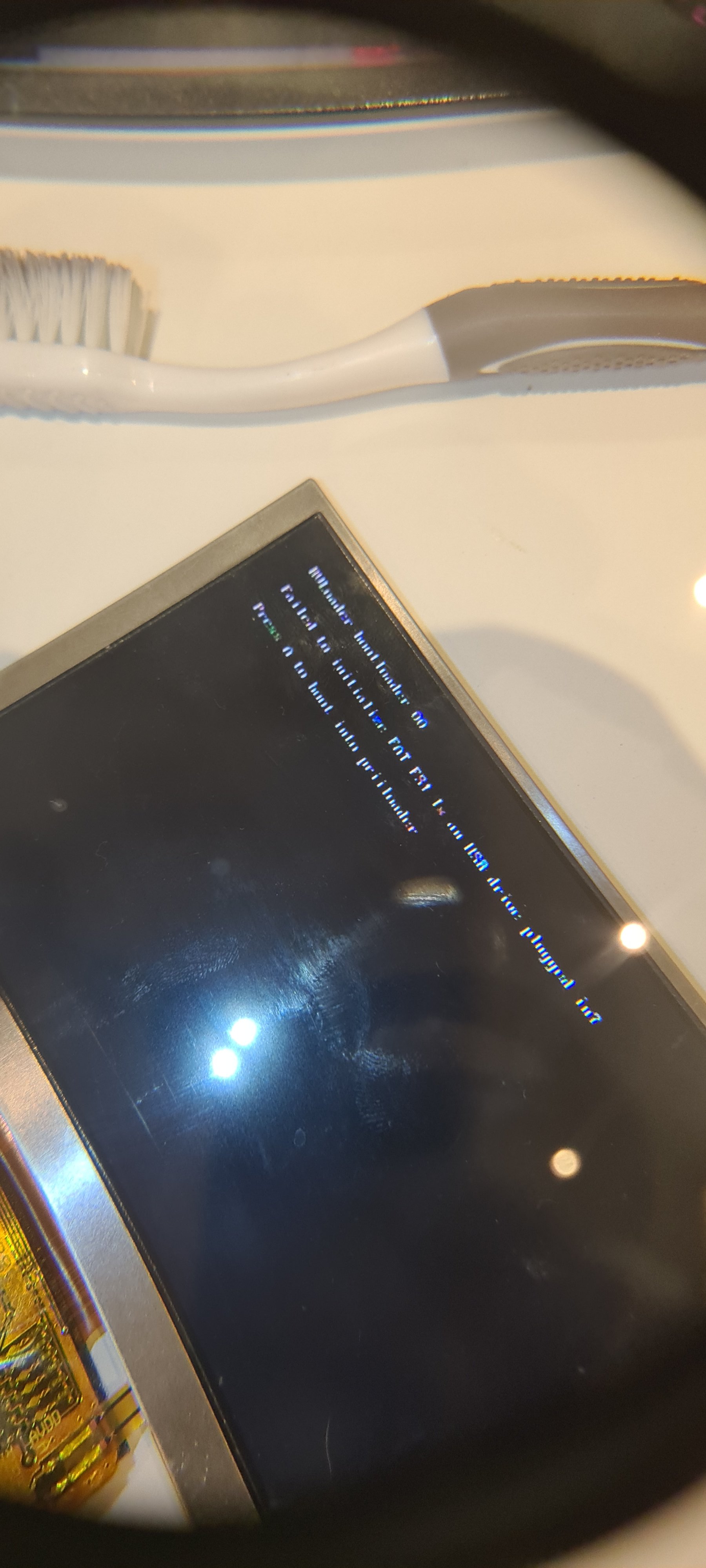
Finally after a lot of issues i had to trim another board and at the end it boot ( so i have 1 board for the PMS2, 1 to fix Couse doesn't have WIFI patch). anyway here i am keeping the fait on this portable by the way thanks to the guys on the 4layer Discord, they have been really helpful on this journey.
Screen test.jpg

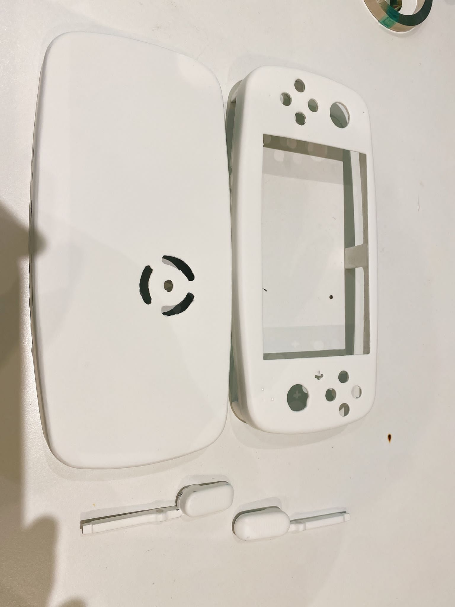
I have been working on the case, doing some mods, painting, sanding over and over almost got the case how i wanted.im using Molotov spray and it seems to be fine.

CASE.jpg


after that i started to work on the batteries ( a big discussion days ago on the Discord channel about the direct battery solder, is not recommended by the way), so i have been checking a lot how to solve this issue on this case but is to small i just managed to place the inside batteries without solder but the outside batteries definitely have to be solder. Also have place and test the L and R triggers and it seems ok, still don't know what is the best tact for those triggers.
Bat+ cal+trigers.jpg
BAT+col.jpg


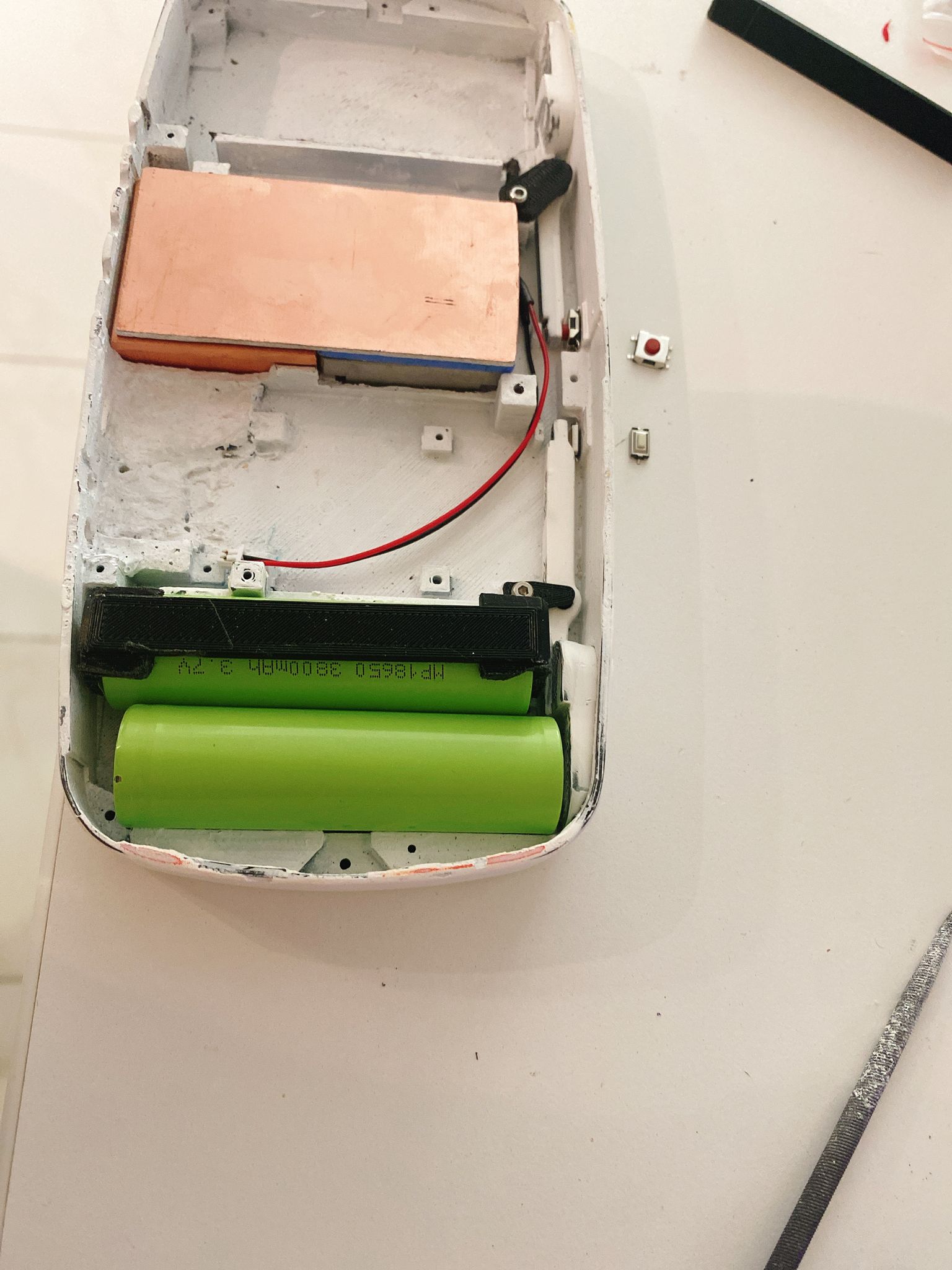
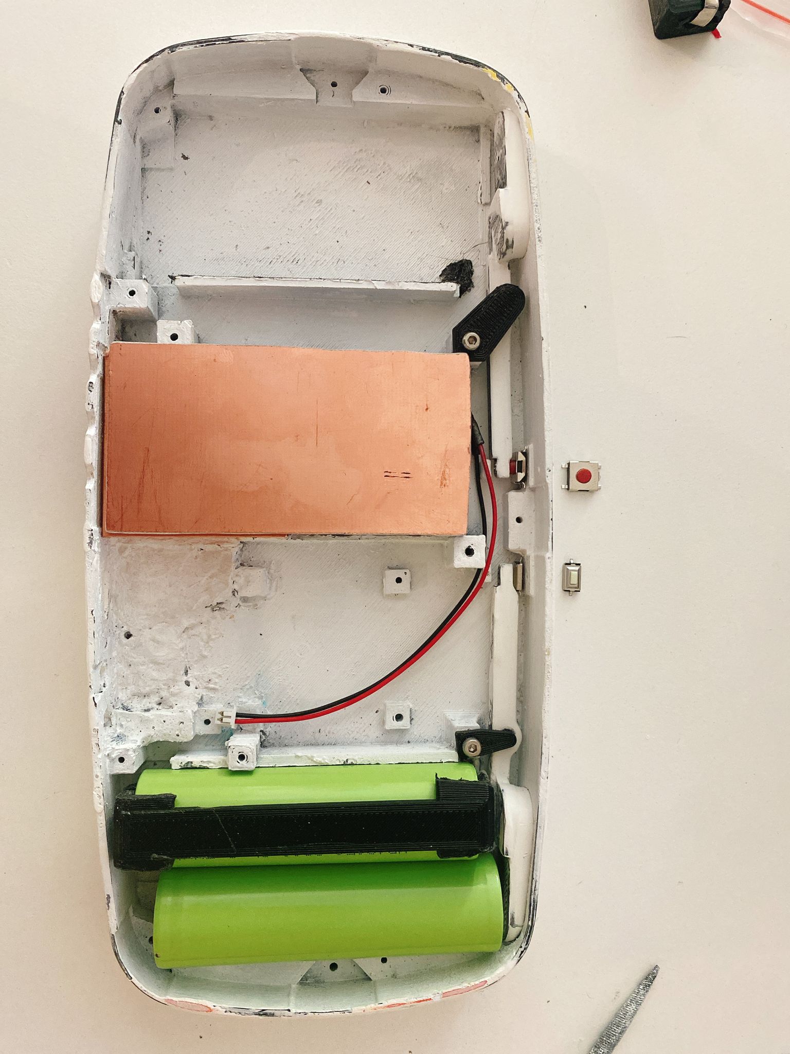
I was wondering if the triggers have to go with the dual tact? and also wich product do you guys use to paste the tacts to the case. superglue or hot glue?

This is all for the moment. things to come USB connection and test+ VGA connection and test so with that complete. I think i can proceed to work on the other side of the case.
 
Last edited:

dababy

.
Joined
Nov 7, 2021
Messages
110
Likes
40
personally i like using hot glue for that. if u do use it though make sure not to put to much or it can be a pain to remove in small places
 

Jpin

.
Joined
Sep 17, 2021
Messages
39
Likes
24
New update.

so here is the update with the USB and VGA working good, also i have wire the SCW and SDW to the board. here are the pics
3.3v connection.(not the best soldered here)
3.3v VGA.jpg

H and V sync.
H nd V sync.jpg

R,B and Y RGV and Screen board.
Screen board.jpg

R,B,Y, VGA.jpg

USB connection.
PD USB.jpg
USB.jpg

VGA test including USB.
VGA Test.jpg

Guys do i need to wire all GND points on the Screen board to the wii or can be done like i did ?

Next step ill put all together inside the case and see how does it work and check what changes should i do.

thanks for reading guys.
 
Joined
Mar 22, 2021
Messages
55
Likes
13
Location
Germany
The other grounds on the screen are analog grounds for the colors, they'll only be useful if you twist the color signal wires with a gnd wire that you then solder onto there, which will improve image quality.
 

Jpin

.
Joined
Sep 17, 2021
Messages
39
Likes
24
Hi guys I’m back with an update.

After having a big issue finding what was the problem, why wii suddenly stop booting after trying to put altogether inside the case, I finally found what was missing here is the pic. i had to change that component and then all went back to normal, thank god.
20220323_161253.jpg

Then @Gingeroofoz announced the release of the new Louii case so I wait for it and finally here I am back on track ready to finish my first portable.

I have 2 questions if anyone knows the answer i must appreciate your help.

1. im using this tacts for the left and right trigger but im wondering if wiring them with only 2 wires is good enough to make them work? i have seem some works were people use 3 wires but is not real clear so i have the doubt and cant find any diagram of this model.
20220408_095549.jpg
20220408_095609.jpg

2. is it possible to get 3v for the screen from other place rather than the PMS lite or is a must that the screen has to be power from the PMS ?

Thanks for reading
 

dababy

.
Joined
Nov 7, 2021
Messages
110
Likes
40
i think u have to wire the screen from rvl pms off the 5v component however it might work to get another regulator to go from batteries directly to the screen but that would waste battery a lot. I think the best option is directly from the pms. as for the tact switches i'd play it safe with them and use 3 wires
 

Jpin

.
Joined
Sep 17, 2021
Messages
39
Likes
24
i think u have to wire the screen from rvl pms off the 5v component however it might work to get another regulator to go from batteries directly to the screen but that would waste battery a lot. I think the best option is directly from the pms. as for the tact switches i'd play it safe with them and use 3 wires
Well I have use the screen with the 3v from the pms and works fine, but since im using the GC +2 and it has a 3v connection I was thinking on using that one but not sure, about the switch do you know where to connect the 3rd wire ?

Thanks for the answer
 

Jpin

.
Joined
Sep 17, 2021
Messages
39
Likes
24
Hi guys here an update on the Louii.

After a long wait on the Dual Tacts to arrive finally came so back to work.

Im starting getting all together inside the case, so first part is the wii with a bit long cables to test the boot without the USB and SCW,SDW and it works. here are some pics
IMG-20220425-WA0006.jpg
IMG-20220425-WA0008.jpg


After this test a went ahead and short the cables, screw the board to the case and wired the USB, SDW,SCW and the RVL-NTC. and the result was just great.
IMG-20220425-WA0010.jpg
IMG-20220425-WA0011.jpg


So things are getting excited, next step will be the other half of the LOUII and continue doing tests every single change i do just to make sure all is working.

Btw What is the normal temperature of the Wii while playing and how can i shield the SDW,SCW wires wich is Gingers recommendation for this build?

Thanks for reading
 
Top