- Joined
- Jul 9, 2020
- Messages
- 230
- Likes
- 500
For the longest time I have wanted to take on this challange. The "illusive omega trim"... After a breif but welcome vacation from wii while diving deep into the n64 project, I'm inspired and ready give this a try. I've been studying the compendium after transferring it over to photoshop.... learning so much! I don't necessarily have a project in mind for an omega trim... i just want to have some fun with it! ")
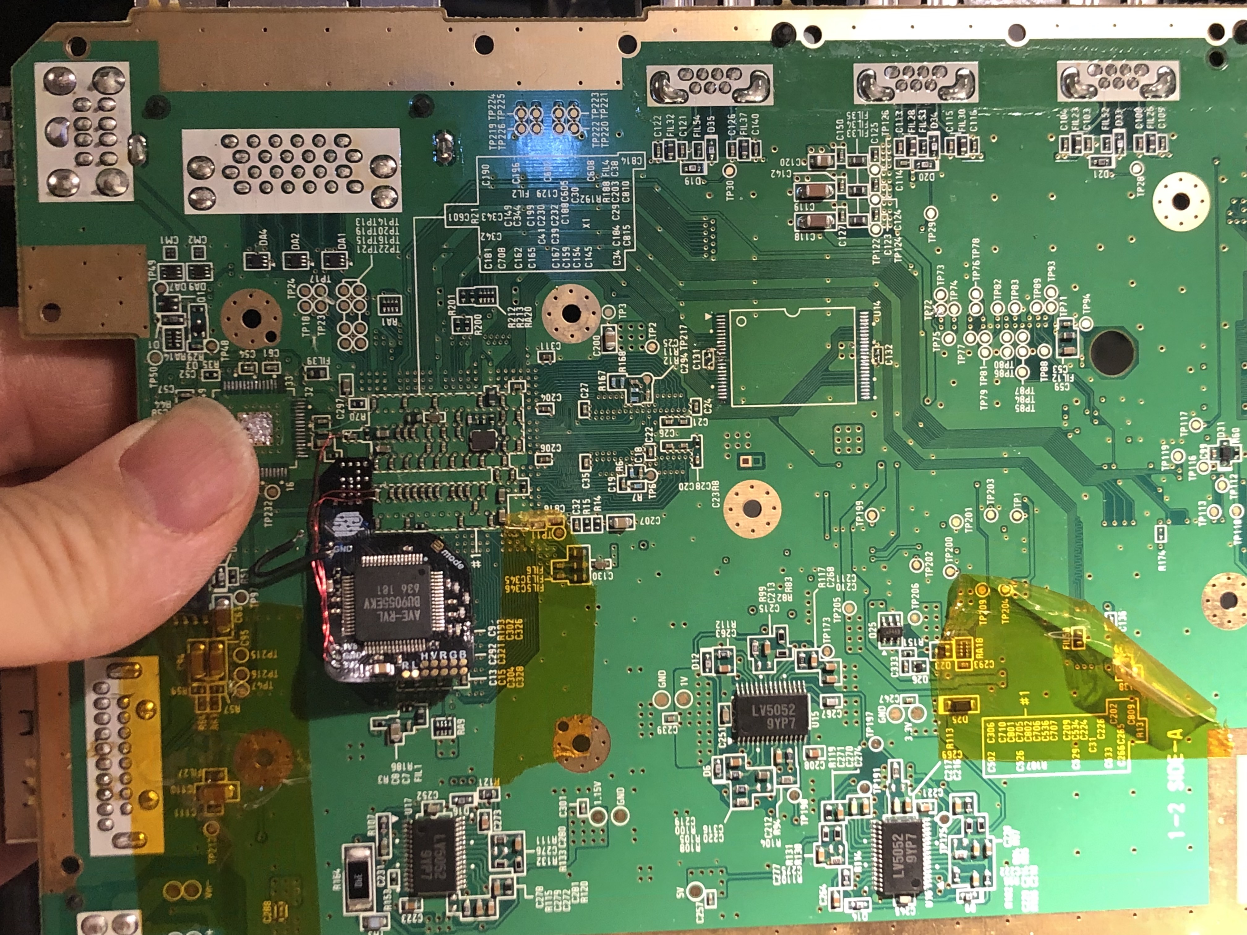
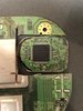
My first attempt last night went a little wacky.. Starting with a verified booting rvloaded board. Next, I tried to desolder the ave chip on an untrimmed board and I broke it. Turns out you need to heat this guy up for nearly 10 minutes in my case... I also relocated u10 in the way I learned from some photos @YveltalGriffin shared with me...
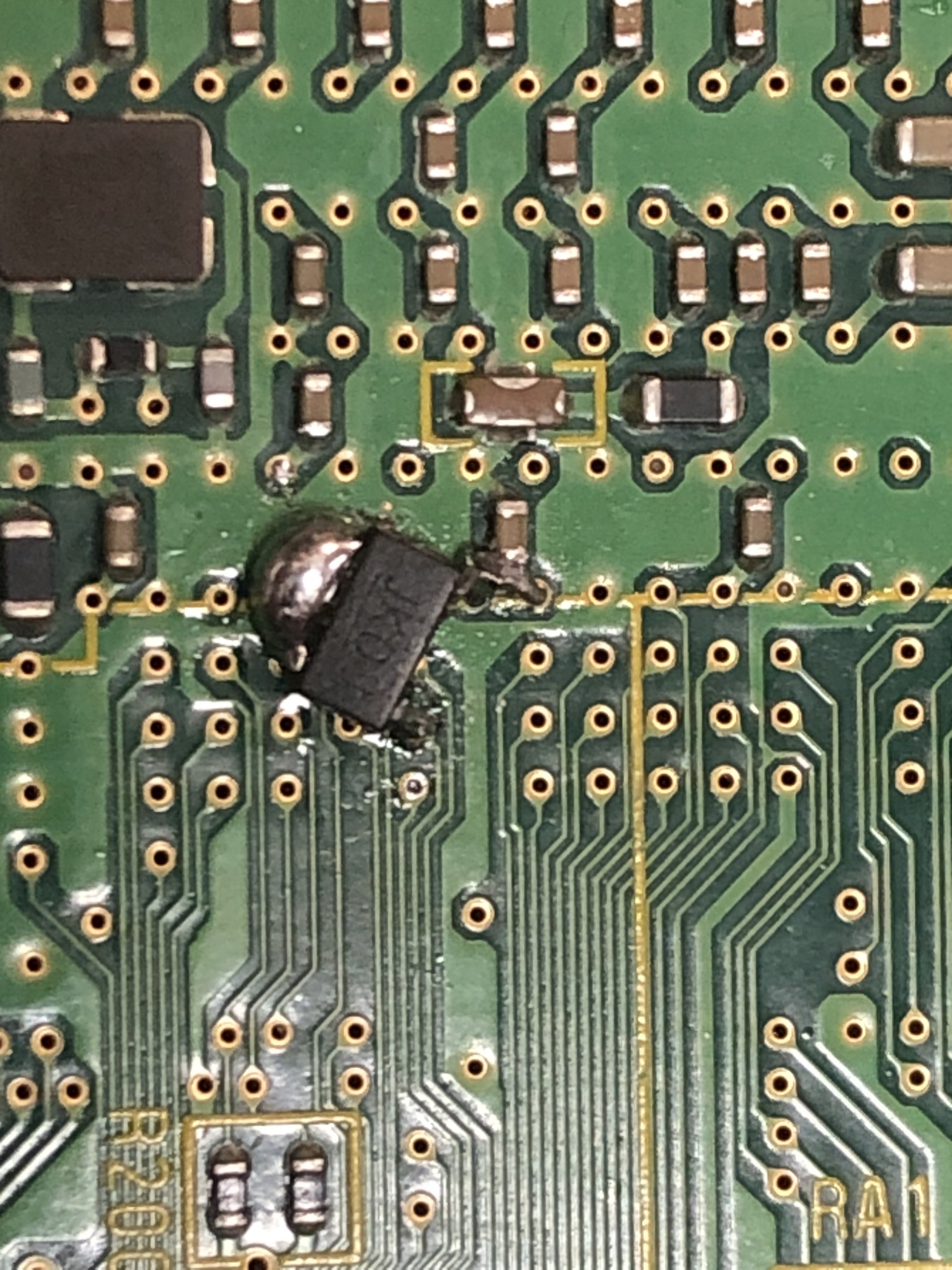
Figured i'd check before moving on and found a short between 3v3 and ground on the board... i could NOT figure out why i even tried to fix it by cutting the ave lines around the footprint of the chip. That also didn't do it... So I just figured trim the board and see what happens... This got rid of the short and figured I was in the clear. This was not ideal for the process of testing after each step but it is what it is.... or was... I tried like 15 times soldering down and desoldering the flex. Finding shorts with the ground every time! ugh! When prepping the vias i accidentally scratched the ground via too big and it was bridging with the surrounding pins. I ended up cutting and filing away some of that exposed ground strip. Eventually I got all the pads down with out shorts and without bridges between anything... but it would still not boot.
In learning how to test this trim @YveltalGriffin gave me these hints:
1. Check for shorts between all quick-solder vias on the fpc
2. Check continuity between every ave pin and the corresponding original pad on the mobo
3. Check for other stuff like shorts to gnd on all pins and vias
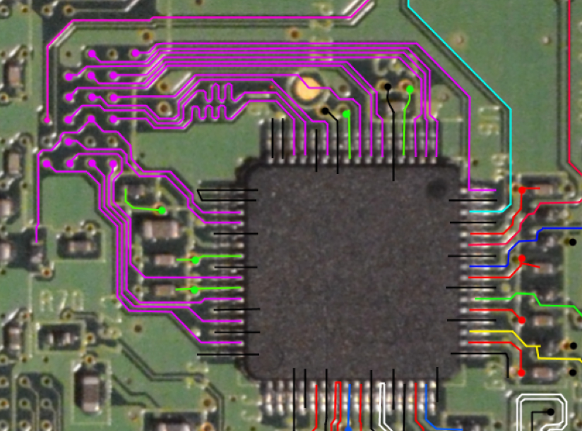
Oh man! I cut the lines around the pads on the original AVE footprint... yikes, this made it so difficult to test the pins. But I scratched off mask to test and eventually confirmed pins were connected to where they were supposed to be. But it STILL would not boot... Hmm... I had to just let it be for the night.
Next morning, After a bit of further testing on the first trimmed attempt, I desoldered the flex and tried testing the trim with an AVE-HDMI I had installed on a different untrimmed wii... I took that other wii apart and desoldered the ave-hdmi lines and transfered it to my trim to test if it would bot without the ave flex in the picture. Alas, that also did not work. I figured I would actually start fresh... and I already had a wii motherboard right there ready from the one that had just recently been severed from the AVE-HDMI.
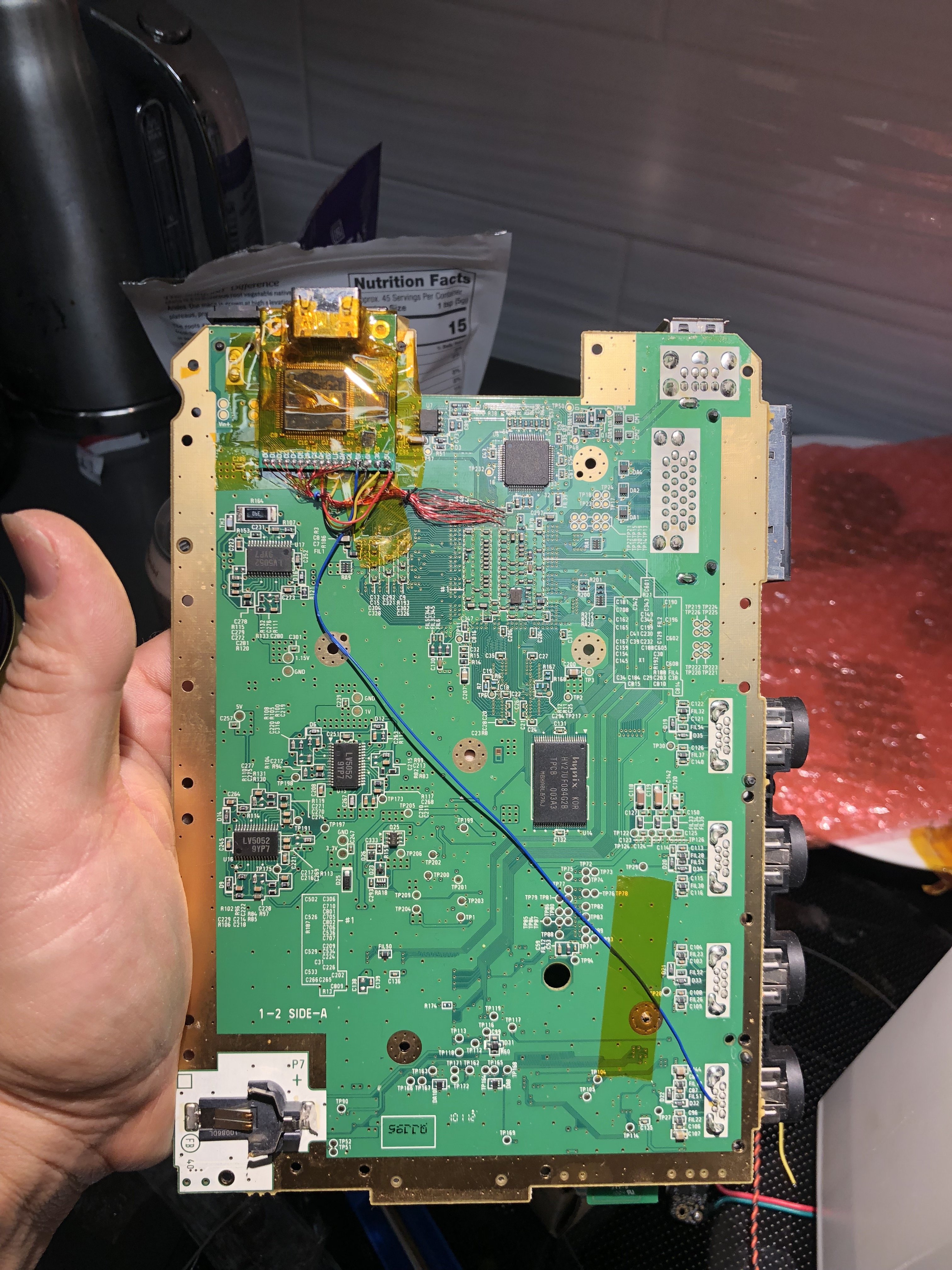
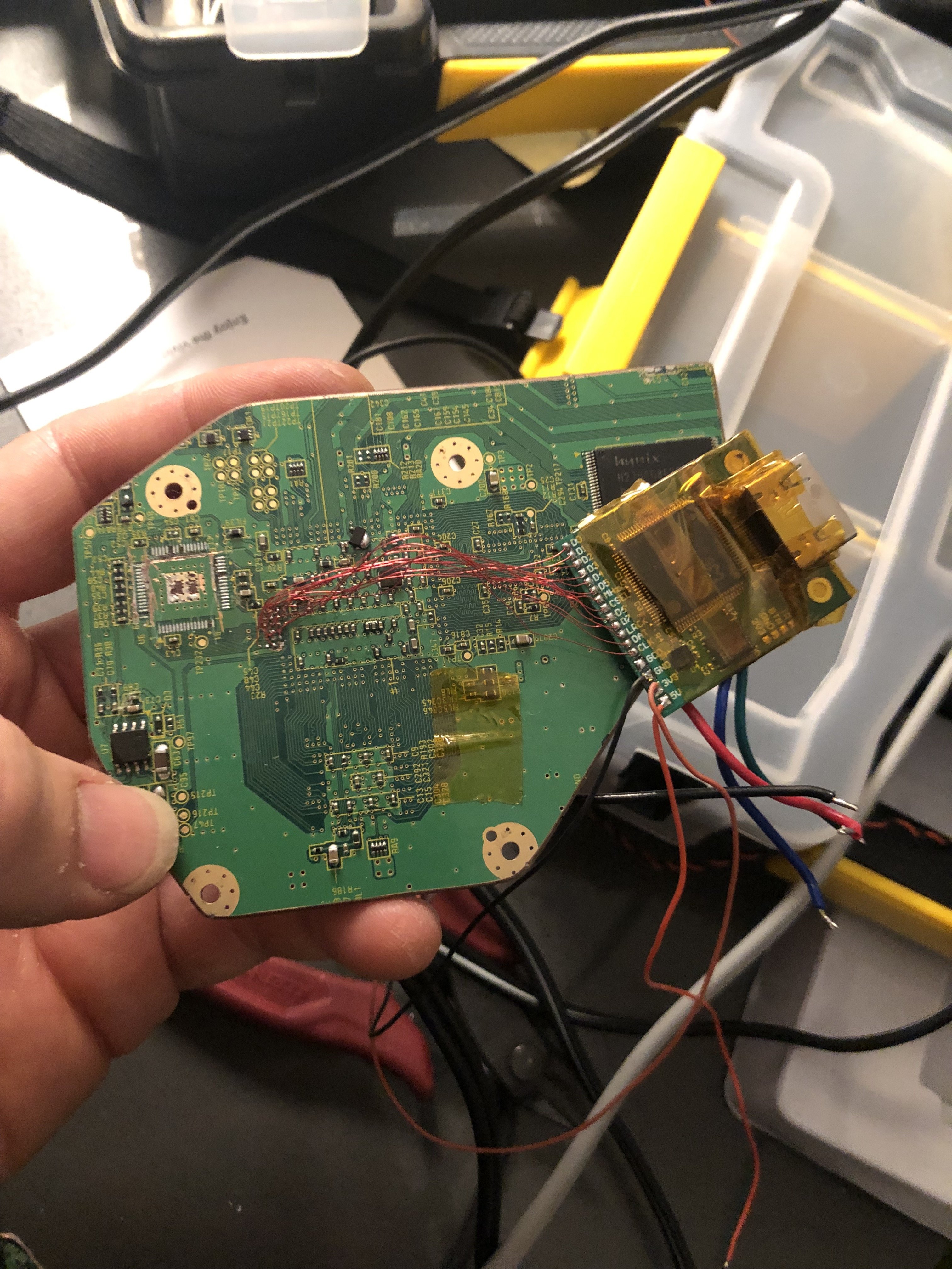
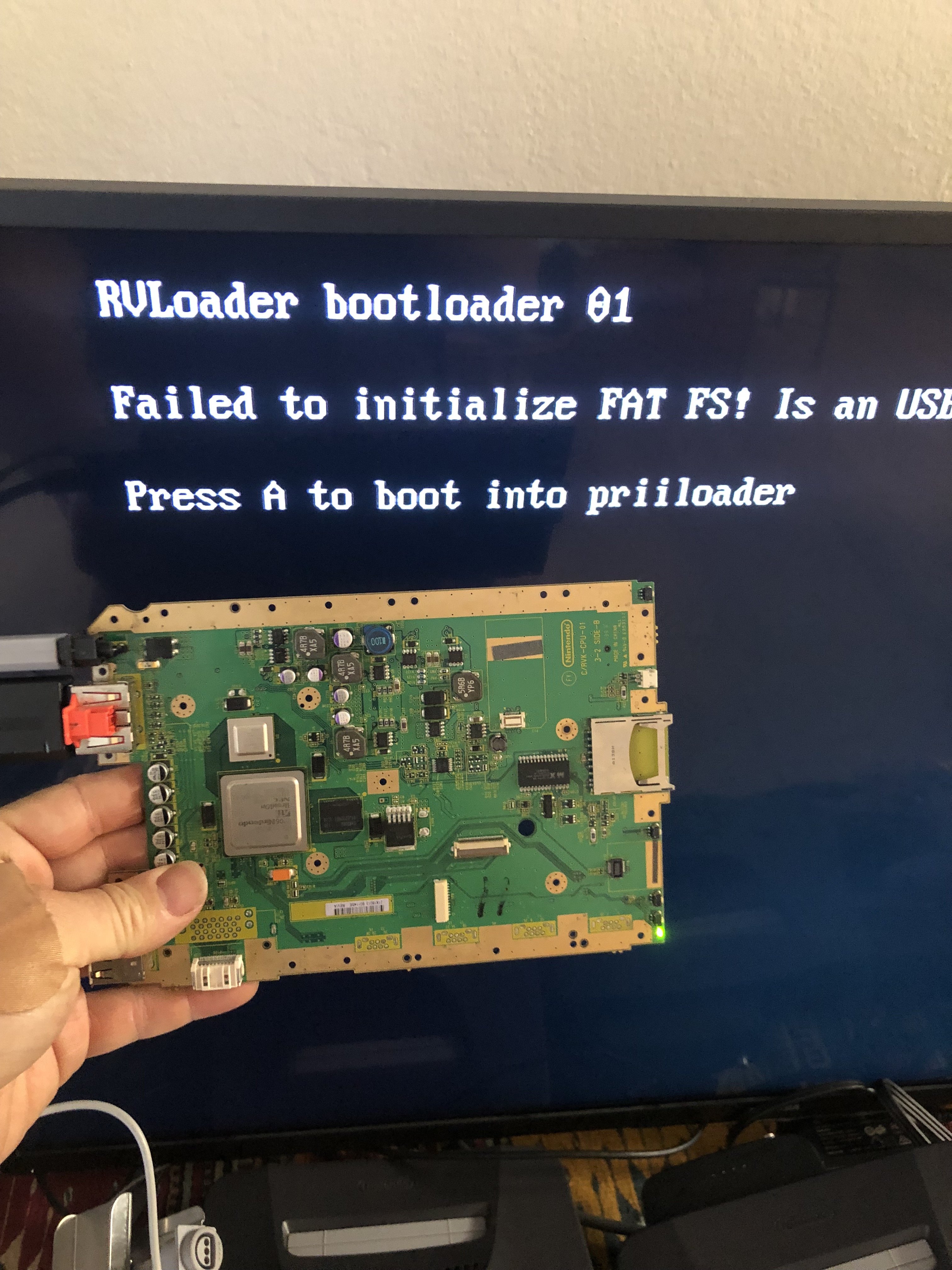
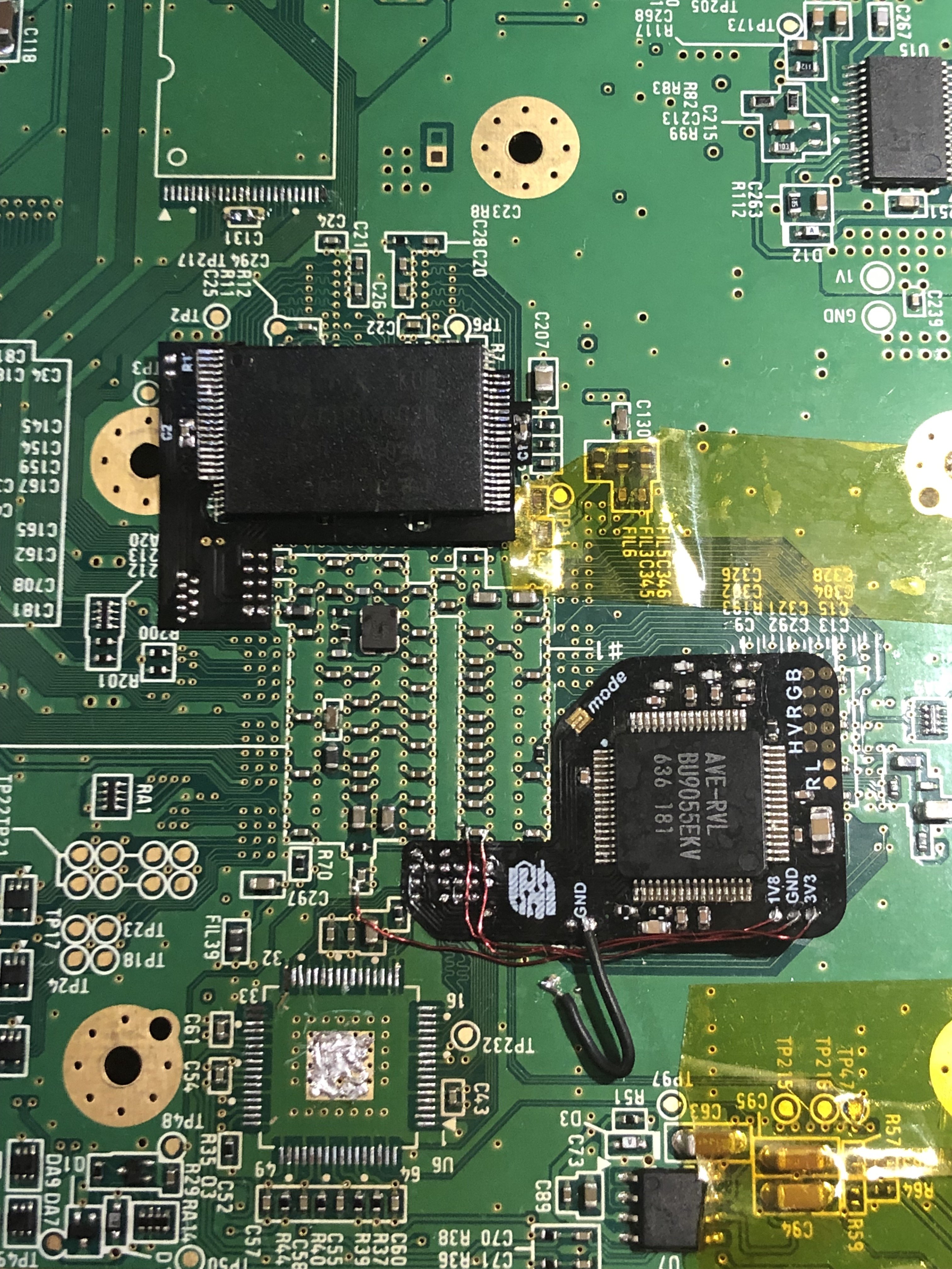
This time I would not jump ahead in the process before testing each step... This new untrimmed wii boots with RVLoader. Check! Next, desolder the AVE. This time I took my time... it took about 12 minutes but eventually it did come up. Phew... No shorts. Keep moving forward. I soldered down the AVE flex after prepping the vias. It went down really easily after all that practice last night... lol.
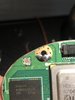
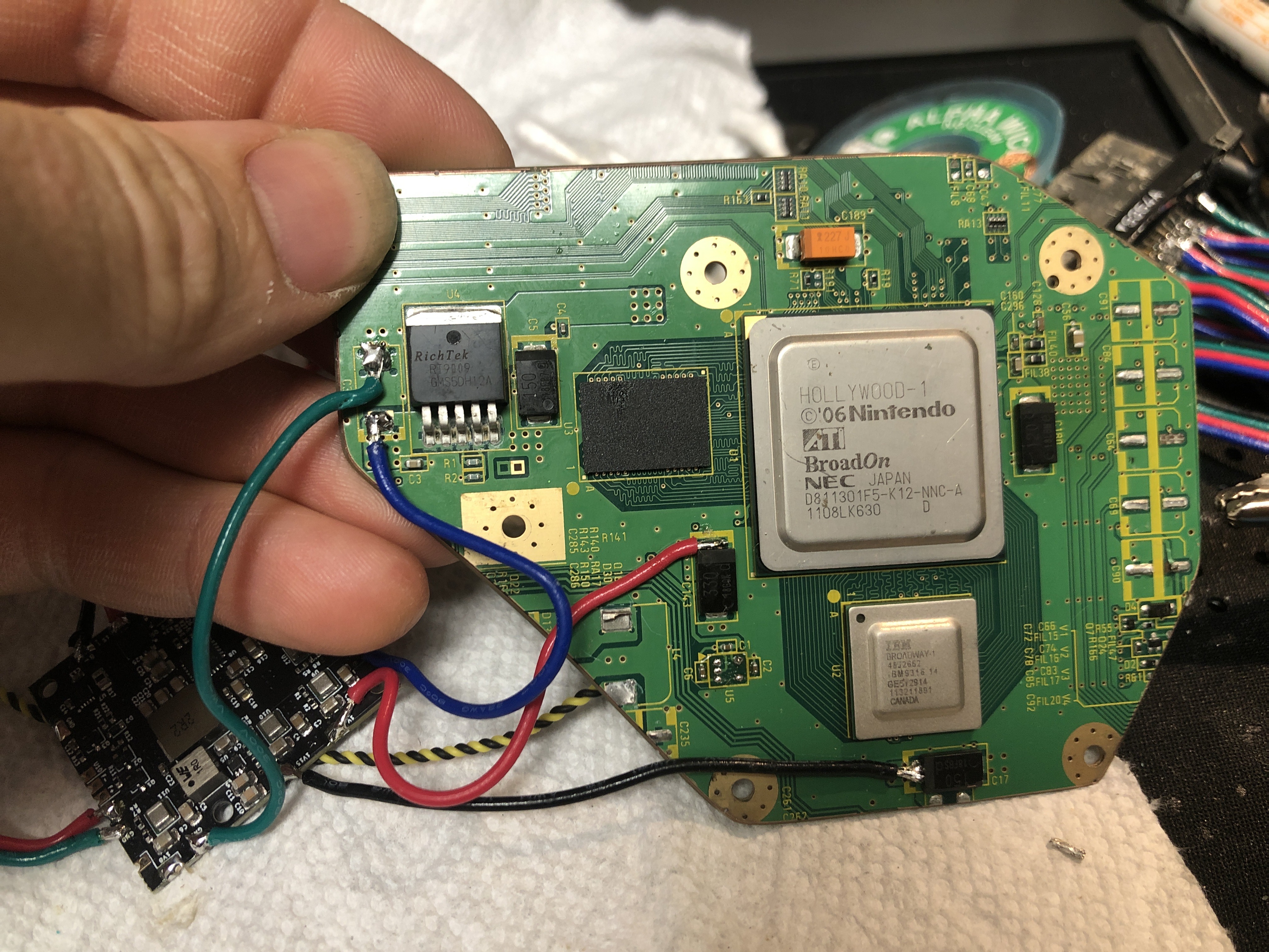
It wouldn't boot, so I tested and tested... Everything was checking out! Every via from pad to flex ave, from via to original footprint pin, from footprint to ave chip on flex; everything was checking out properly! Voltages where they were supposed to be... everything!!! I even added an extra ground wire. Then it dawned on me... the console I took apart was my home console months ago and I used to use WIFI for homebrew! I DIDN'T PATCH OUT WIFI!!! I put the wifi chip on the board and it boots! WOOOT!
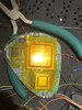
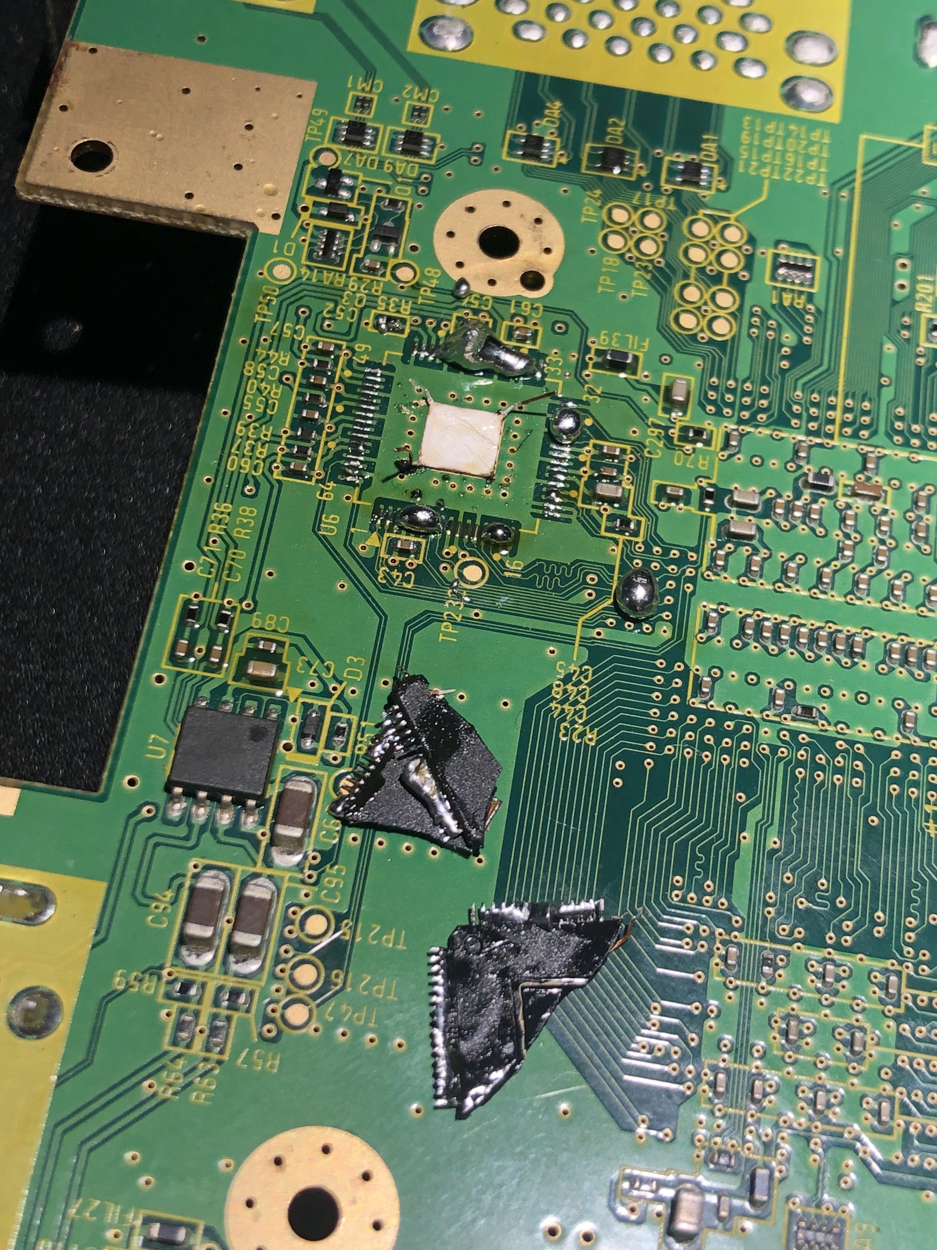
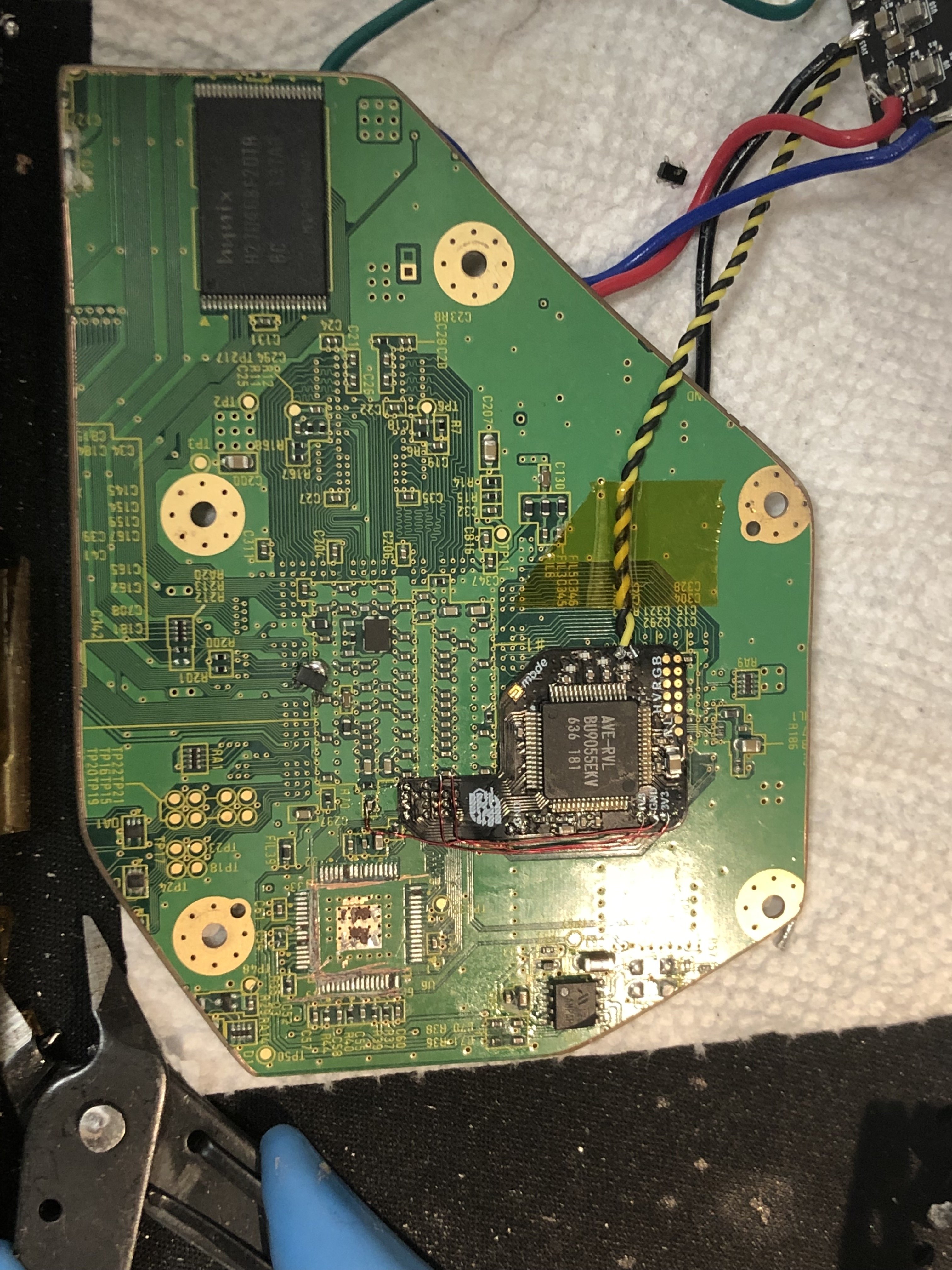
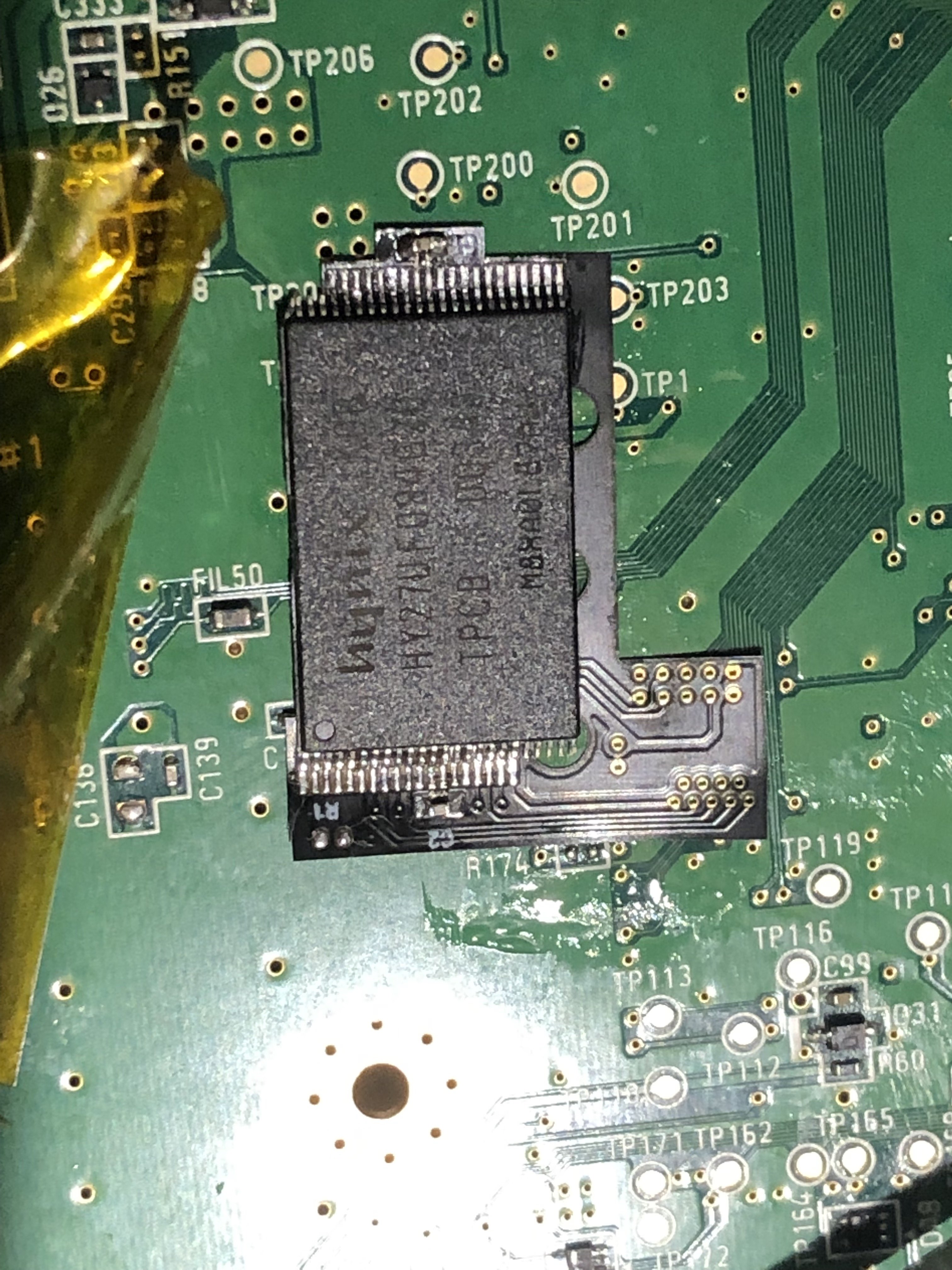
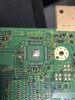
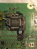
I couldn't just leave it like that so I moved on to the NAND relocation. Fired up the hot air and started blasting the chip at 375c full air flow...... another 10 minutes later the chip lifted! Prepped the 4layer tech NAND flex with some flux and solder, cleaned it up, taped it down, lined up the NAND and tacked the top and bottom corner and checked alignment. Looked good! With a healthy dose of flux and a magnifying glass I used the soldering iron to drag from each pin and away to set them onto the flex. Desoldered the two ceramic caps and added them to the flex too. Cleaned of all the flux residue with a good IPA bath and scrub... squeaky clean and shiny!
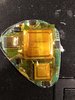
Prepped the NAND vias with a bit of scraping and tinned them up. I soldered them down using amtech flux and cleaned up my mess after... Tried to boot with no success. Then discovered those two little vias i missed. Woops! Lets not forget that little pair next time! I also realized I needed to relocate C200 to the front of the board... Nice.
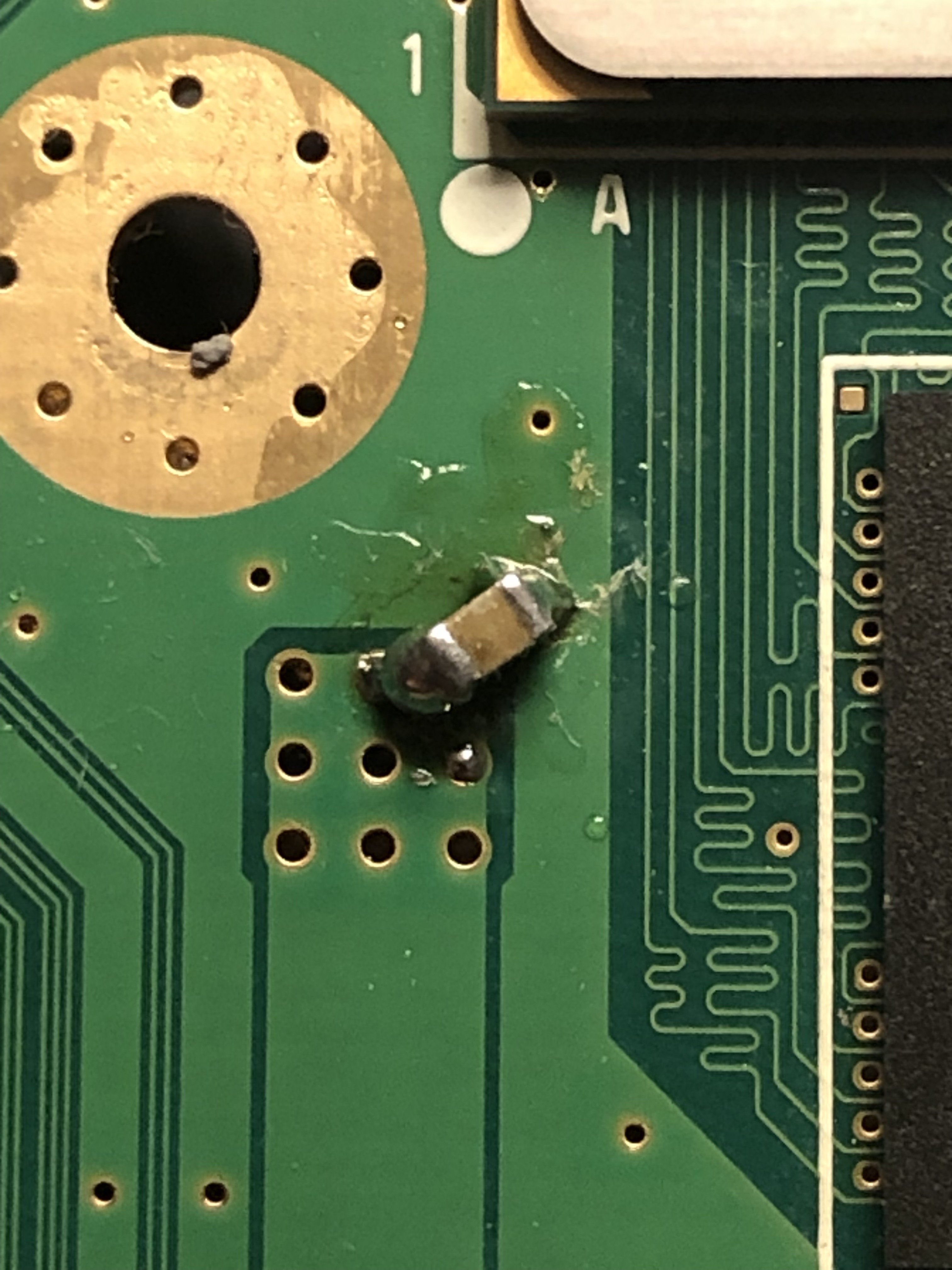
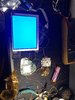
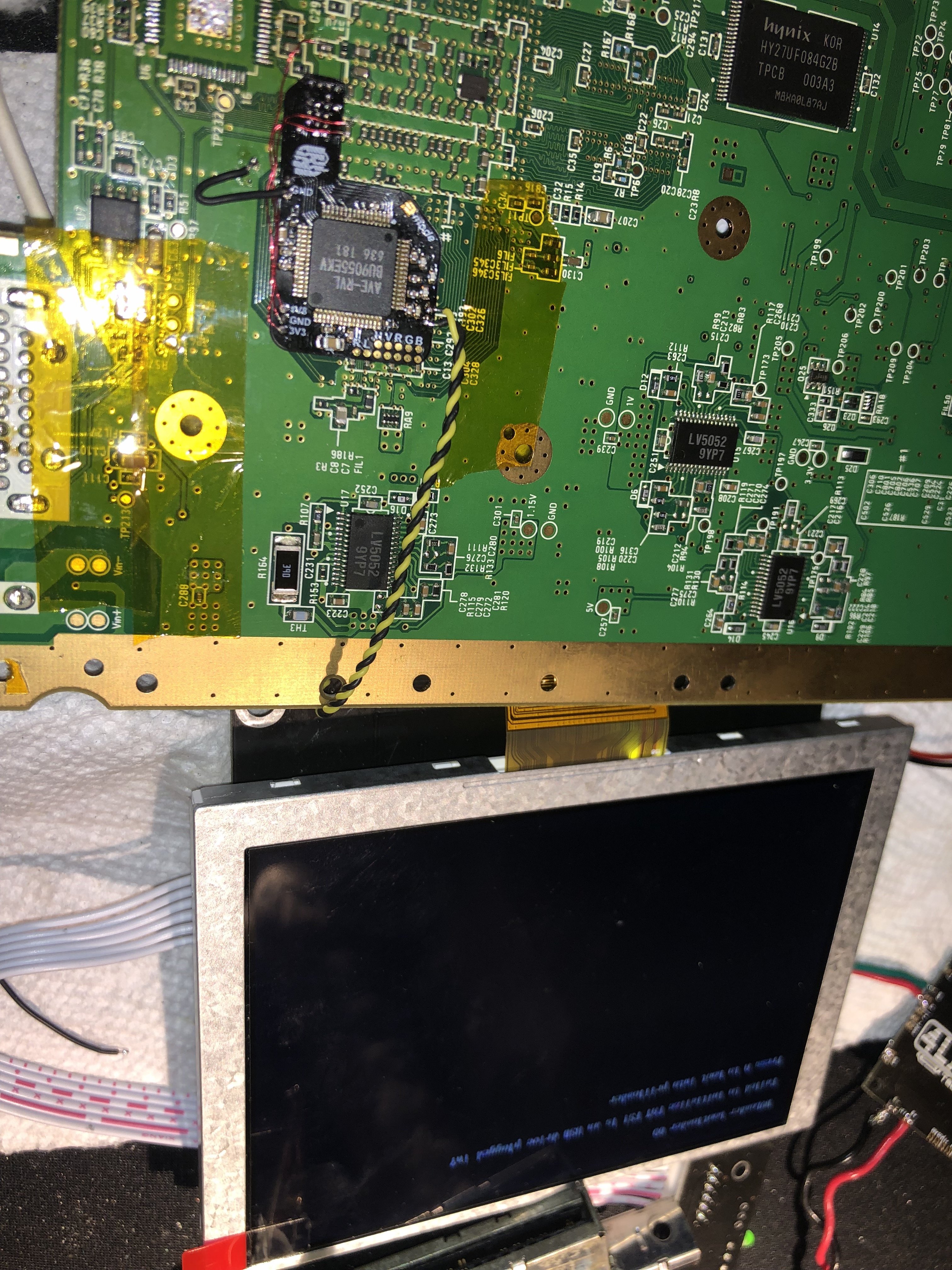
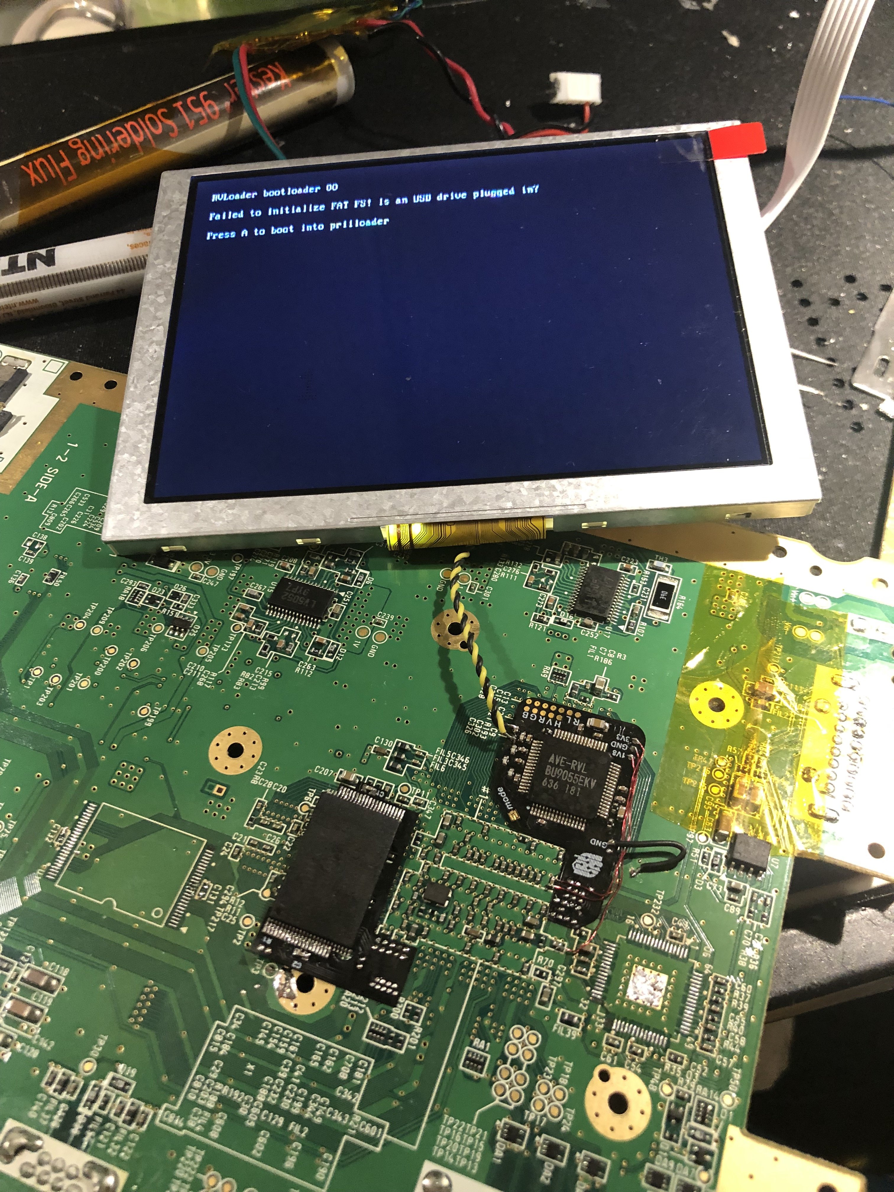
Tacked down those two unsoldered pads to the vias... Cleaned it off again and trim booted right up! Turns out I was not able to get video out of the main video output... but when I soldered to the composite out on the flex it was fine... *shrug*
So, thats where I am at so far... its now 1/4 to 3am and this was obviously too important to get to sleep early over. ;P
Stay tuned.
My first attempt last night went a little wacky.. Starting with a verified booting rvloaded board. Next, I tried to desolder the ave chip on an untrimmed board and I broke it. Turns out you need to heat this guy up for nearly 10 minutes in my case... I also relocated u10 in the way I learned from some photos @YveltalGriffin shared with me...
Figured i'd check before moving on and found a short between 3v3 and ground on the board... i could NOT figure out why i even tried to fix it by cutting the ave lines around the footprint of the chip. That also didn't do it... So I just figured trim the board and see what happens... This got rid of the short and figured I was in the clear. This was not ideal for the process of testing after each step but it is what it is.... or was... I tried like 15 times soldering down and desoldering the flex. Finding shorts with the ground every time! ugh! When prepping the vias i accidentally scratched the ground via too big and it was bridging with the surrounding pins. I ended up cutting and filing away some of that exposed ground strip. Eventually I got all the pads down with out shorts and without bridges between anything... but it would still not boot.
In learning how to test this trim @YveltalGriffin gave me these hints:
1. Check for shorts between all quick-solder vias on the fpc
2. Check continuity between every ave pin and the corresponding original pad on the mobo
3. Check for other stuff like shorts to gnd on all pins and vias
Oh man! I cut the lines around the pads on the original AVE footprint... yikes, this made it so difficult to test the pins. But I scratched off mask to test and eventually confirmed pins were connected to where they were supposed to be. But it STILL would not boot... Hmm... I had to just let it be for the night.
Next morning, After a bit of further testing on the first trimmed attempt, I desoldered the flex and tried testing the trim with an AVE-HDMI I had installed on a different untrimmed wii... I took that other wii apart and desoldered the ave-hdmi lines and transfered it to my trim to test if it would bot without the ave flex in the picture. Alas, that also did not work. I figured I would actually start fresh... and I already had a wii motherboard right there ready from the one that had just recently been severed from the AVE-HDMI.
This time I would not jump ahead in the process before testing each step... This new untrimmed wii boots with RVLoader. Check! Next, desolder the AVE. This time I took my time... it took about 12 minutes but eventually it did come up. Phew... No shorts. Keep moving forward. I soldered down the AVE flex after prepping the vias. It went down really easily after all that practice last night... lol.
It wouldn't boot, so I tested and tested... Everything was checking out! Every via from pad to flex ave, from via to original footprint pin, from footprint to ave chip on flex; everything was checking out properly! Voltages where they were supposed to be... everything!!! I even added an extra ground wire. Then it dawned on me... the console I took apart was my home console months ago and I used to use WIFI for homebrew! I DIDN'T PATCH OUT WIFI!!! I put the wifi chip on the board and it boots! WOOOT!
I couldn't just leave it like that so I moved on to the NAND relocation. Fired up the hot air and started blasting the chip at 375c full air flow...... another 10 minutes later the chip lifted! Prepped the 4layer tech NAND flex with some flux and solder, cleaned it up, taped it down, lined up the NAND and tacked the top and bottom corner and checked alignment. Looked good! With a healthy dose of flux and a magnifying glass I used the soldering iron to drag from each pin and away to set them onto the flex. Desoldered the two ceramic caps and added them to the flex too. Cleaned of all the flux residue with a good IPA bath and scrub... squeaky clean and shiny!
Prepped the NAND vias with a bit of scraping and tinned them up. I soldered them down using amtech flux and cleaned up my mess after... Tried to boot with no success. Then discovered those two little vias i missed. Woops! Lets not forget that little pair next time! I also realized I needed to relocate C200 to the front of the board... Nice.
Tacked down those two unsoldered pads to the vias... Cleaned it off again and trim booted right up! Turns out I was not able to get video out of the main video output... but when I soldered to the composite out on the flex it was fine... *shrug*
So, thats where I am at so far... its now 1/4 to 3am and this was obviously too important to get to sleep early over. ;P
Stay tuned.
Attachments
-
 1.7 MB Views: 271
 -
 1.7 MB Views: 237
 -
 1.8 MB Views: 228