Hi community:
I'm from Spain and newbie in this fantastic community, I'm working on my first personal project, that is integrate a travel router to make use of the SAMBA protocol to share games, and replace the CD / DVD drive with a SATA disk (it can be a HDD or SSD) which its USB to SATA adapter is attached directly to the router, to be able to use the bandwith of the ethernet port (100 Mbps or 12MB/s theorically).
I'm using these components for this project:
*PlayStation 2 Slim PAL model SCPH-77004
*GL-iNet MT300N-V2 router with the lastest OpenWrt 21.03 system flashed.
*USB to SATA uGreen adapter, which is UAS (USB Attached SCSI) and capable to use USB 2.0 and 3.0 protocols.
*DC-DC stepdown Mini 560 buck with 5V output to power the travel router and the USB to SATA adapter, each one are powered with 5V and 1A, well, the power for the USB to SATA adapter depends more of the SATA device attached to it, but in general, a 2.5" SATA disk is powered with 1A.
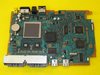
Well, I need to know which is the best component or solder point from where to take the 8.5V to provide to the DC-DC stepdown the IN line (and of course, its corresponding GND), with the security that the ampers taken from that solder point / component doesn't make any negative impact in the PlayStation 2.
I hope that you can understand me well, I'm so sorry for my english, is not my native language, if you need more info or something, don't hesitate to say it and I will try to give you that info / explanation that you need, thanks in advance for your help.
I'm from Spain and newbie in this fantastic community, I'm working on my first personal project, that is integrate a travel router to make use of the SAMBA protocol to share games, and replace the CD / DVD drive with a SATA disk (it can be a HDD or SSD) which its USB to SATA adapter is attached directly to the router, to be able to use the bandwith of the ethernet port (100 Mbps or 12MB/s theorically).
I'm using these components for this project:
*PlayStation 2 Slim PAL model SCPH-77004
*GL-iNet MT300N-V2 router with the lastest OpenWrt 21.03 system flashed.
*USB to SATA uGreen adapter, which is UAS (USB Attached SCSI) and capable to use USB 2.0 and 3.0 protocols.
*DC-DC stepdown Mini 560 buck with 5V output to power the travel router and the USB to SATA adapter, each one are powered with 5V and 1A, well, the power for the USB to SATA adapter depends more of the SATA device attached to it, but in general, a 2.5" SATA disk is powered with 1A.
Well, I need to know which is the best component or solder point from where to take the 8.5V to provide to the DC-DC stepdown the IN line (and of course, its corresponding GND), with the security that the ampers taken from that solder point / component doesn't make any negative impact in the PlayStation 2.
I hope that you can understand me well, I'm so sorry for my english, is not my native language, if you need more info or something, don't hesitate to say it and I will try to give you that info / explanation that you need, thanks in advance for your help.
Last edited: