Hi everyone!
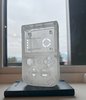
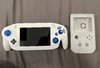
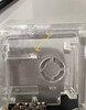
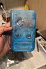
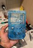
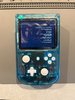
Its almost 2024 and a perfect time to build a G-boy! or should I say the The G-Boy Rev4U! I'm making this a translucent shell with blue/white buttons so I'm calling it Glacier Ice!
I have always wanted to build the Gboy from movement I saw it. Unfortunately I'm a little bit late for the official kit. But the spirit of the G-boy lives on thanks to you all!
This was also my first time ordering custom pcb so that was a really cool experience!
Useful Links:
4Layer Technologies
DustinFisher updated the Rev3 case files
CrazyGadget list of helpful links
Curtismods edited case files
TMHF07 squishy tacts for L/R
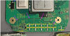
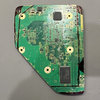
Trim:
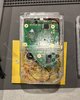
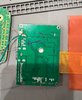
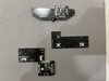
Pretty standard old 4layer wii from ebay. I did rip out the entire copper trace from one of the filtration caps. I though the motherboard was done for! After carefully looking over the traces It seems that I dont really need it. Phew!")
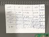
I may have been overcautious marking the initial trim lines. I spent a solid 2 days Trimming--->Sanding--->Ipa bath---->Resistance check to get my trim to fit into the case (in theory)
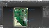
I have a ghetto method of checking my trim in 3ds max since my case prints aren't here yet.
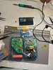
Trim test:
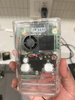
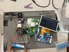
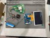
I hooked up all voltage line and connected the Composite lines to the 3.5 inch screen (JT035IPS02-V0) and powered it on. The fan spun up, the cpu was warm but no display. I even hooked up a button to the pcb to change source to AV. Fun fact, the 3.5 inch screen (JT035IPS02-V0) in the BOM does not support composite. I tried it with a spare 4layer screen & It worked first try!
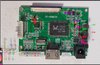
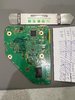
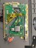
Populating PCBs:
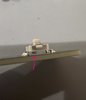
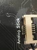
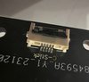
Pretty straightforward. I noticed that the squishy tacts (TMHF07) don't sit flush on the pcb bored. I had to solder them like this to get them to align. I might desolder and clip the tiny extrusions. I also hope the switch joystick connectors are soldered well. They are really tiny and a pain to solder!
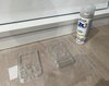
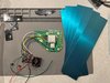
I may have ordered the wrong copper sheets. This one is a tad big.
That is all for now. Thanks and Happy Holidays!")
Its almost 2024 and a perfect time to build a G-boy! or should I say the The G-Boy Rev4U! I'm making this a translucent shell with blue/white buttons so I'm calling it Glacier Ice!
I have always wanted to build the Gboy from movement I saw it. Unfortunately I'm a little bit late for the official kit. But the spirit of the G-boy lives on thanks to you all!
This was also my first time ordering custom pcb so that was a really cool experience!
Useful Links:
4Layer Technologies
DustinFisher updated the Rev3 case files
CrazyGadget list of helpful links
Curtismods edited case files
TMHF07 squishy tacts for L/R
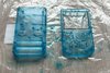
Trim:
Pretty standard old 4layer wii from ebay. I did rip out the entire copper trace from one of the filtration caps. I though the motherboard was done for! After carefully looking over the traces It seems that I dont really need it. Phew!
I may have been overcautious marking the initial trim lines. I spent a solid 2 days Trimming--->Sanding--->Ipa bath---->Resistance check to get my trim to fit into the case (in theory)
I have a ghetto method of checking my trim in 3ds max since my case prints aren't here yet.
Trim test:
I hooked up all voltage line and connected the Composite lines to the 3.5 inch screen (JT035IPS02-V0) and powered it on. The fan spun up, the cpu was warm but no display. I even hooked up a button to the pcb to change source to AV. Fun fact, the 3.5 inch screen (JT035IPS02-V0) in the BOM does not support composite. I tried it with a spare 4layer screen & It worked first try!
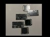
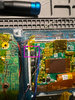
Populating PCBs:
Pretty straightforward. I noticed that the squishy tacts (TMHF07) don't sit flush on the pcb bored. I had to solder them like this to get them to align. I might desolder and clip the tiny extrusions. I also hope the switch joystick connectors are soldered well. They are really tiny and a pain to solder!
I may have ordered the wrong copper sheets. This one is a tad big.
That is all for now. Thanks and Happy Holidays!