
- Joined
- Jan 15, 2021
- Messages
- 48
- Likes
- 105
- Location
- Not quite socialist North Europe
- Portables
- GB Adwiince v2
Heya ^^
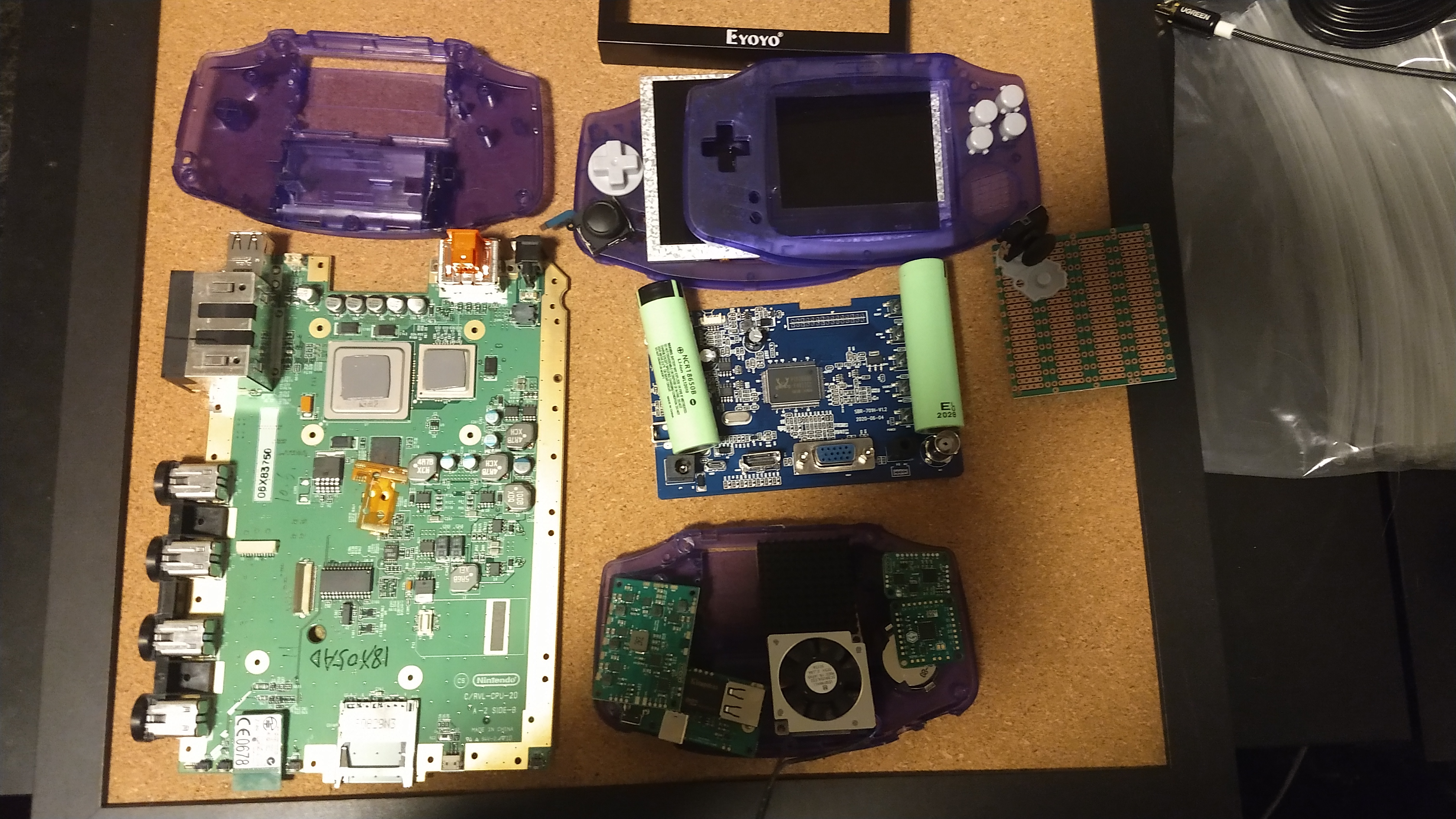
All my parts finally arrived, so it is time to make a worklog and start this project properly.
I plan to frankencase two GameBoy advance shells together to fit the 5" component Eyoyo display. And then have all the other components within the GBA shell.
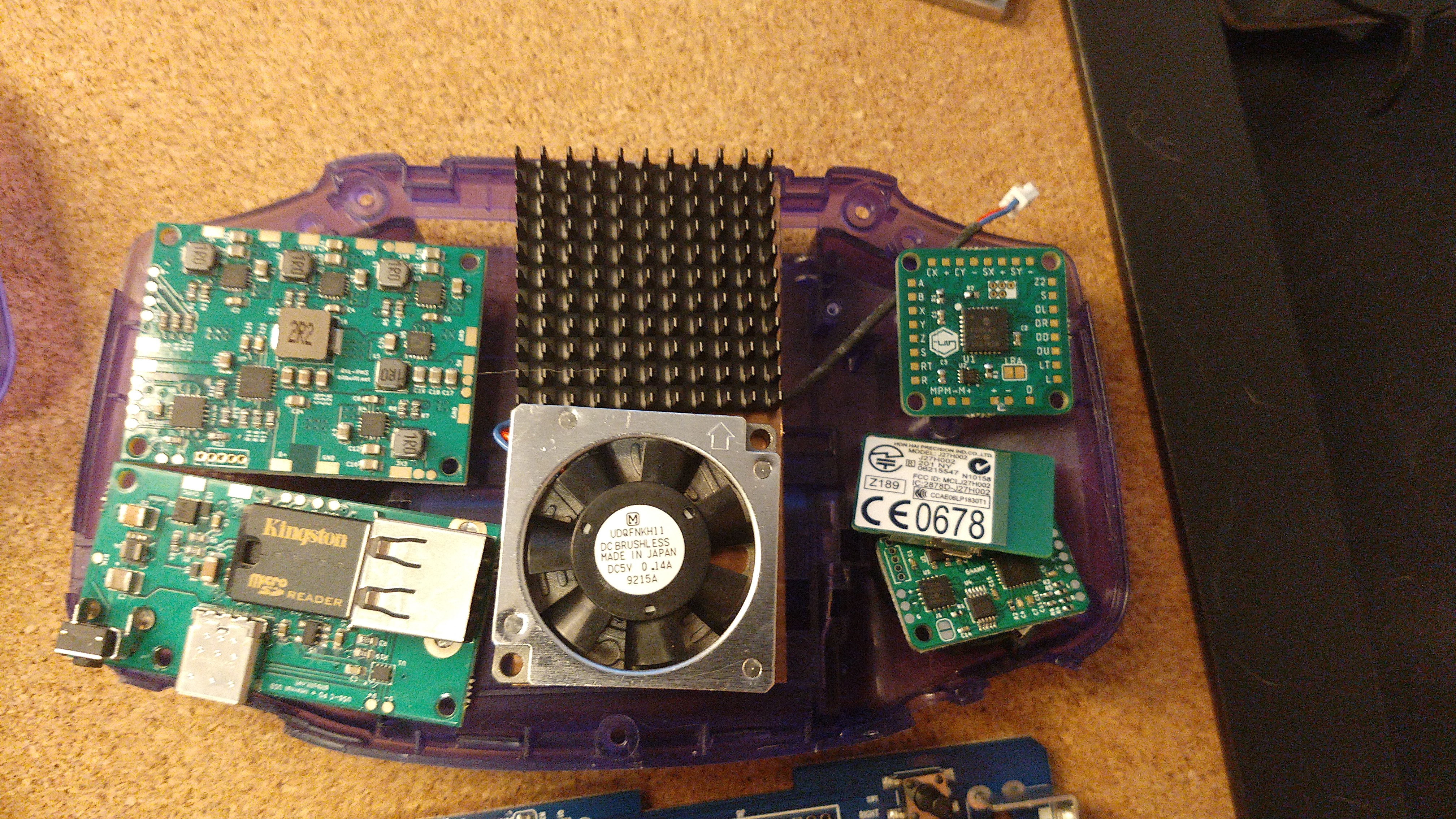
My biggest worry is the thickness, especially the middle part where I'm squeezing in the LCD, driver board, cut Wii, and cooling on top of each other. And that the batteries won't fit on either side of the motherboard, on top of the driver board, though I'm not super attached to the batteries and will drop them if they don't fit.
Edit: It seems the PMS requires batteries to work, so I'll have to properly factor them in, I'll probably have to cut slots into the back of the case so they can stick out a bit. Or try to find some of those flat cell batteries.
I'll be using my 6 layer board, as life hit me with a sledgehammer right after ordering all the other parts, so I can't responsibly shill out more money than I already have. At least not for the next few months till my life situation gets more stable.
Anyway, so I'll just use this 6 layer board I already had. If the heat or energy demand is too high, then *shrug* I'll at least have gotten some more practice working with electronics on such a small scale.
I plan to do a lmao cut on it. I'll start with the Nand relocation, first moving it to the flex PCB, then rewiring it to fit the 6 layer board. When I get that working, I'll do the Omgwtf cut with power relocation, before doing the actual Lmao cut, so that I can test each step properly. If you ask why do a lmao cut on a 6 layer board. Well, because yolo, I felt like trying it, that's why. XP
Edit: I just found a black wii for 30$ in my area. So I'll try to get that one, so I don't have to manually rewire the Nand. I'll still aim for the lmao cut.
Also, as I was too impatient to wait for the U-Amp to come back in stock, I ended up buying the 64 amp instead (sorry, not sorry). So I will flash it back to the u-amp firmware, separate IVDD from 3.3v, and remove the master clock generator as I can just solder in that signal directly. (And then hope I didn't miss any other changes between the u-amp and the 64-amp)
Edit: Doing this would be insane. It seemed feasible from just looking at the pcb schematics, but seeing the scale of it and the precision needed (and the chips are not identical), and the low chance of it succeeding, when there is already the backup of analogue in. It would just be insanity to actually try it. So analogue in it is.
Other than that, it's rather normal stuff, GC+ for the internal controller, the RVL PMS, and USB C changing combo. I'll use the GBA buttons, d-pad, shoulder buttons (with the two-state switches from BB) and then add in the switch joysticks underneath. I plan to reuse one of the tactile switched from the driver board as a Z button underneath the regular shoulder buttons.
If possible, I'll try to include extra features like Bluetooth, MX chip, and component out,though like batteries, they will be optional for me, and I'll drop them if there is no space.
Here is my initial plan for the layout. Though, I'll have to remove all the unnecessary plastic and expand the shell properly before I can be sure of the actual layout. (The cooling will, of course be laying down and not up in the actual build.)
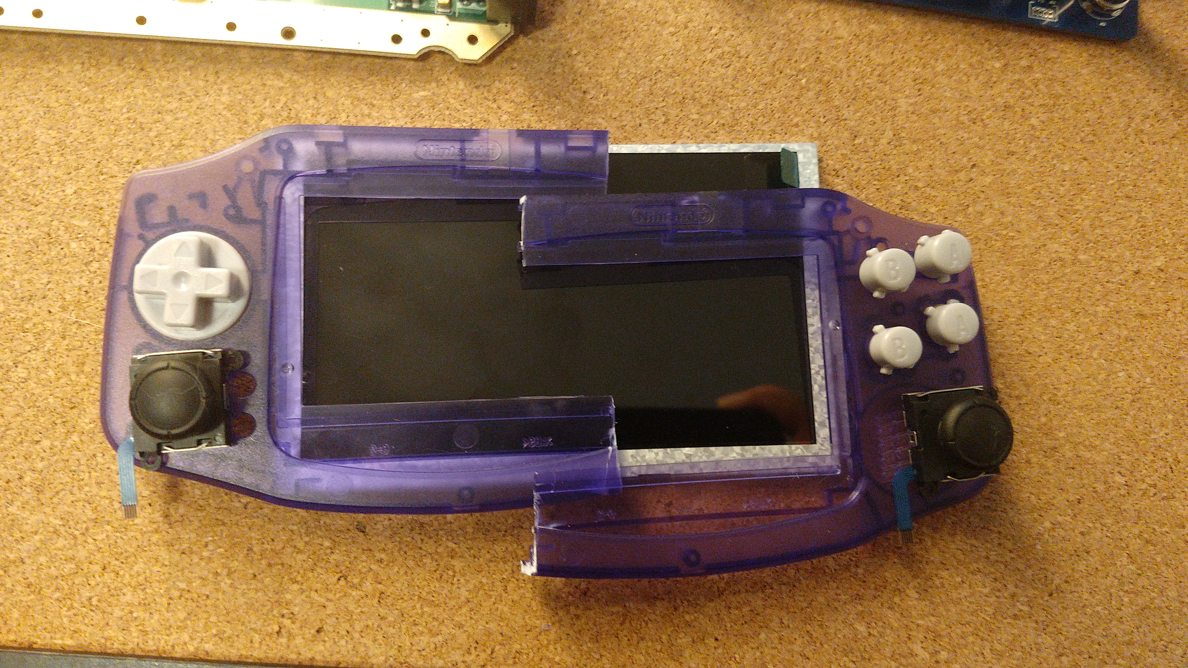
I made a rough cut to better visualize how the two parts of the shell will mesh up. The height of the display in the corners is just barely within what the shell can handle. I had measured it out beforehand based on the description specs, but seeing how close it was is something else. (Also, I know the cuts were not all that great, I'm experimenting with what tools gives the best/cleanest results)
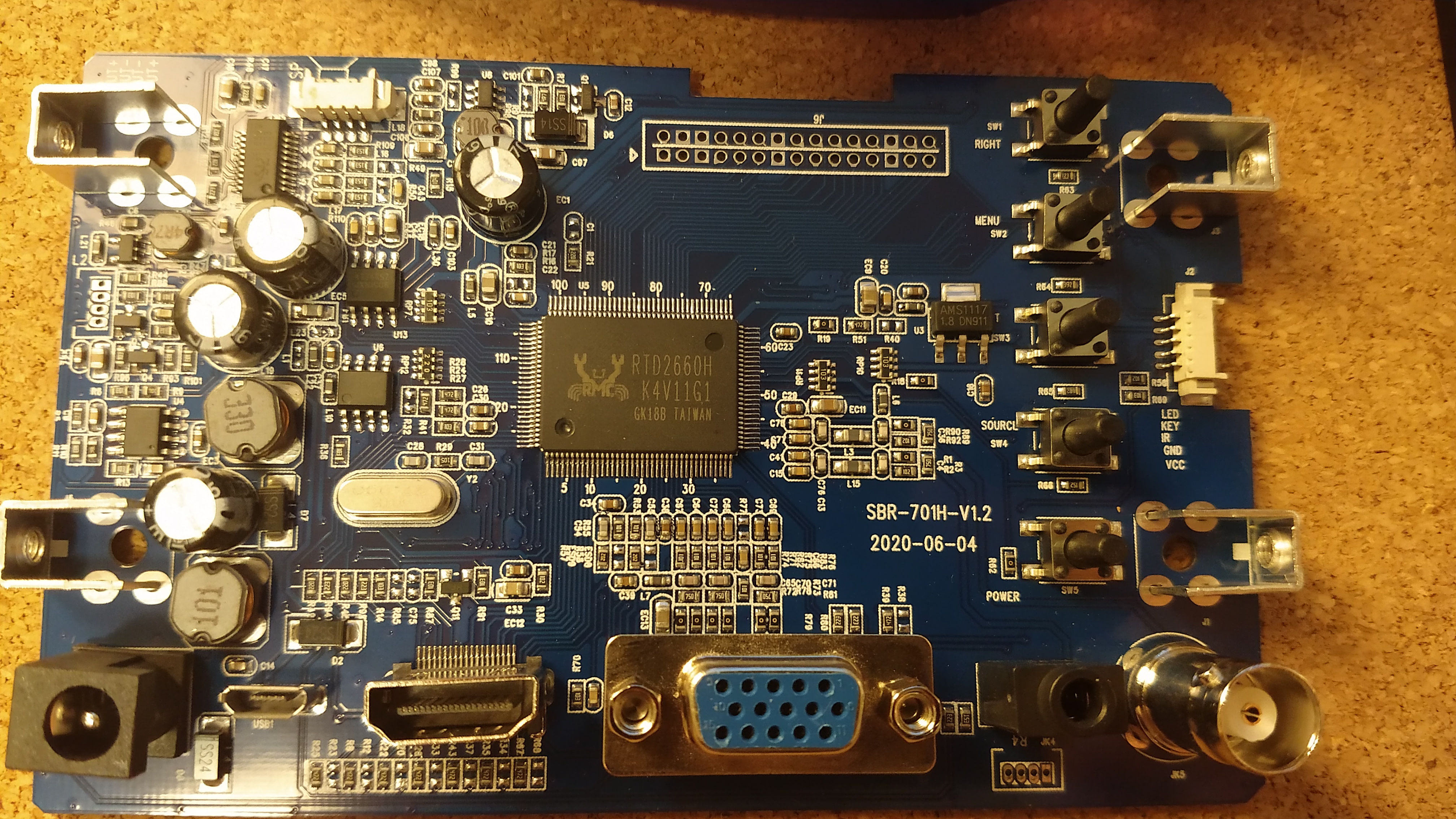
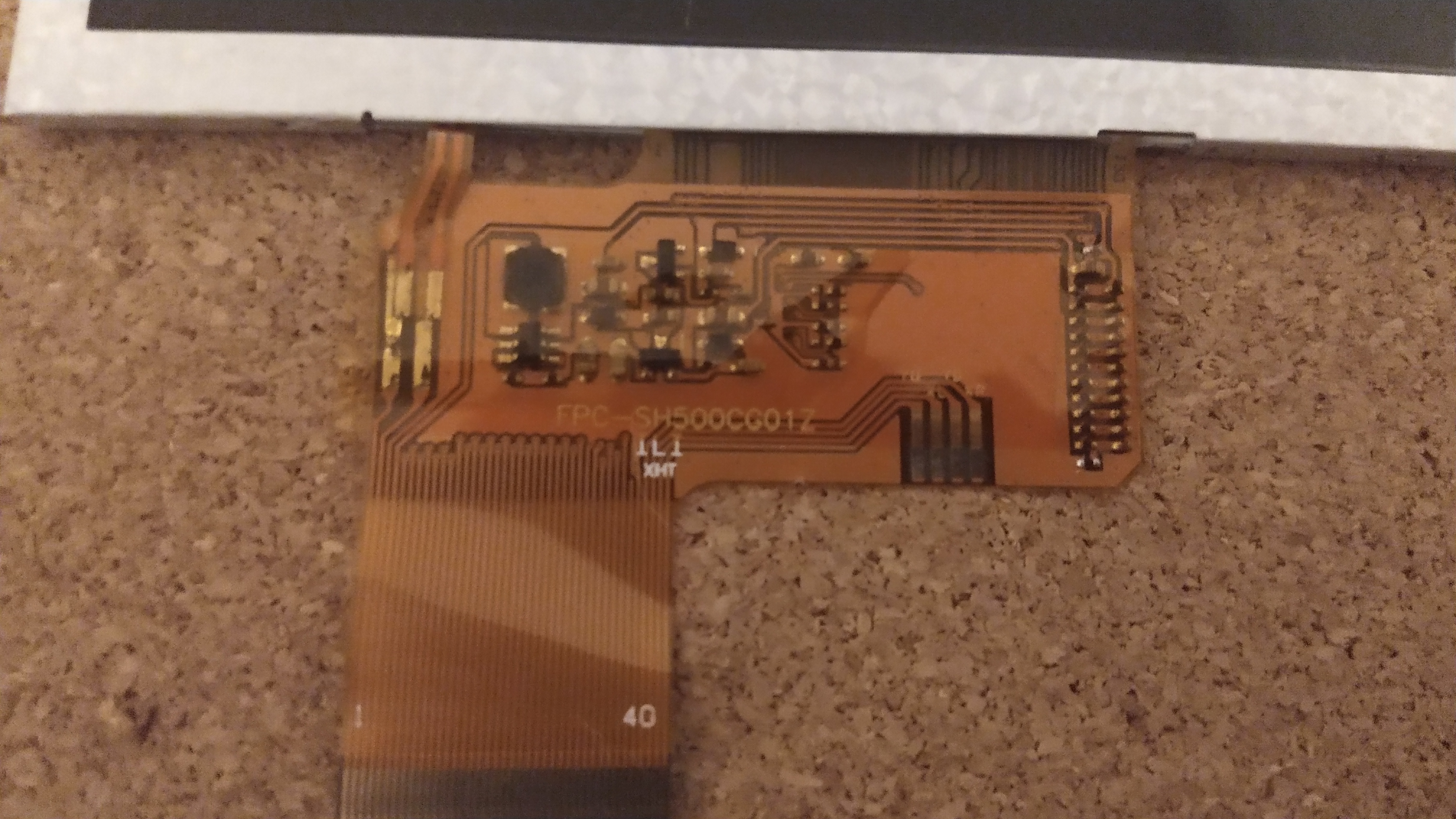
I also noticed that Eyoyo made a new revision to their driver board in 2020. I'll try to grab the firmware in case anyone is going to want it. I feel I have seen both this exact board and the LCD on eBay when I was looking for displays before I found the tread on Eyoyo. So maybe other displays can be converted to accept component video?
Edit: Well I killed this board by rushing a bit too much when removing some of the capacitors, one of them blew, and other important parts flew everywhere. Waiting on a replacement.
All my parts finally arrived, so it is time to make a worklog and start this project properly.
I plan to frankencase two GameBoy advance shells together to fit the 5" component Eyoyo display. And then have all the other components within the GBA shell.
My biggest worry is the thickness, especially the middle part where I'm squeezing in the LCD, driver board, cut Wii, and cooling on top of each other. And that the batteries won't fit on either side of the motherboard, on top of the driver board,
Edit: It seems the PMS requires batteries to work, so I'll have to properly factor them in, I'll probably have to cut slots into the back of the case so they can stick out a bit. Or try to find some of those flat cell batteries.
Anyway, so I'll just use this 6 layer board I already had. If the heat or energy demand is too high, then *shrug* I'll at least have gotten some more practice working with electronics on such a small scale.
I plan to do a lmao cut on it. I'll start with the Nand relocation, first moving it to the flex PCB, then rewiring it to fit the 6 layer board. When I get that working, I'll do the Omgwtf cut with power relocation, before doing the actual Lmao cut, so that I can test each step properly. If you ask why do a lmao cut on a 6 layer board. Well, because yolo, I felt like trying it, that's why. XP
Edit: I just found a black wii for 30$ in my area. So I'll try to get that one, so I don't have to manually rewire the Nand. I'll still aim for the lmao cut.
Also, as I was too impatient to wait for the U-Amp to come back in stock, I ended up buying the 64 amp instead (sorry, not sorry).
Edit: Doing this would be insane. It seemed feasible from just looking at the pcb schematics, but seeing the scale of it and the precision needed (and the chips are not identical), and the low chance of it succeeding, when there is already the backup of analogue in. It would just be insanity to actually try it. So analogue in it is.
Other than that, it's rather normal stuff, GC+ for the internal controller, the RVL PMS, and USB C changing combo. I'll use the GBA buttons, d-pad, shoulder buttons (with the two-state switches from BB) and then add in the switch joysticks underneath. I plan to reuse one of the tactile switched from the driver board as a Z button underneath the regular shoulder buttons.
If possible, I'll try to include extra features like Bluetooth, MX chip, and component out,
Here is my initial plan for the layout. Though, I'll have to remove all the unnecessary plastic and expand the shell properly before I can be sure of the actual layout. (The cooling will, of course be laying down and not up in the actual build.)
I made a rough cut to better visualize how the two parts of the shell will mesh up. The height of the display in the corners is just barely within what the shell can handle. I had measured it out beforehand based on the description specs, but seeing how close it was is something else. (Also, I know the cuts were not all that great, I'm experimenting with what tools gives the best/cleanest results)
I also noticed that Eyoyo made a new revision to their driver board in 2020. I'll try to grab the firmware in case anyone is going to want it. I feel I have seen both this exact board and the LCD on eBay when I was looking for displays before I found the tread on Eyoyo. So maybe other displays can be converted to accept component video?
Edit: Well I killed this board by rushing a bit too much when removing some of the capacitors, one of them blew, and other important parts flew everywhere. Waiting on a replacement.
Last edited: