Question DS Lite Bluetooth Mod?

Joined
Jul 5, 2023
Messages
6
Likes
0
Location
Australia
Hello everyone!

I want to do a bluetooth mod on my DS Lite. I'm having trouble finding a suitable audio L + R point to solder the chip to.

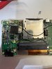
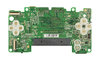
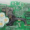
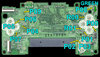
Looking at the top photo of the motherboard, I know the SPL0 and SPR0 are the positive terminals for the speakers. I don't want the volume of the bluetooth device to be controlled via the volume slider though, which SPL0 and SPR0 are.

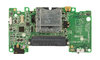
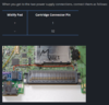
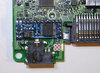
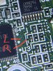
On the bottom photo of the motherboard, could I use the points around the Volume Slider? I think VR3 is the Variable Resistor for the volume but I'm unsure where to solder to. I would guess it should either be 3 & 4 or 1 & 2 around VR3.

Nintendo-DS-Lite-Motherboard-Bottom.jpgNintendo-DS-Lite-Motherboard-Top.jpg
 

Stitches

2 and a Half Dollarydoos
Staff member
.
.
Joined
Feb 5, 2017
Messages
3,848
Likes
3,026
Location
Banana Bender Land, Australia
Portables
6
I'm not sure, but it should be simple enough to find out. If you have a multimeter, you can check for continuity between the SP pads and the legs of VR3. If 2 of the legs have direct continuity, then VR3 is probably a log taper potentiometer. Then you'd just have to set the pot to full volume and probe the opposing legs to find which is the input for L and R, and wire your BT inputs there. Removing the slider may be needed to get the best signal quality.
 
Joined
Jul 5, 2023
Messages
6
Likes
0
Location
Australia
Thanks for the tip!

I'm starting to think that desoldering the speakers and making this a bluetooth-only build will be the simplest solution.

The other option would be to use button switches to turn the speakers on/off but that gets messy with shell modifications required.
 
Joined
Jul 7, 2023
Messages
3
Likes
1
I am currently doing exactly the same mod and I need the LR audio without needing to do a headphone jack hack l. I haven’t been able to find any pads for this. Also where are you planning on soldering your voltage and ground?
Thanks to this thread I found this forum, and registered to reply to this
 
Joined
Jul 5, 2023
Messages
6
Likes
0
Location
Australia
@LDigital, I'm still waiting for parts to arrive before starting. Let me know how you go with your mod in the meantime though! My plan is detailed below.

Audio Ground I'm planning to use VGND or the bottom left leg of the audio jack. Examples in the first two attachments.

Power I'm planning to use the Slot 2 Cartridge Connector Pins 1 and 32 or the BT- and BT+. Examples in the next two attachments.

In terms of chip, I went with the KCX_BT_EMITTER V1.7. I'm planning to position this on the left of the Slot 2 Cartridge Connector with double sided tape. Example of position in the fifth image.

I'm thinking the bluetooth pairing function can be soldered to P02 (Select Button). Location shown in the last image.

My inspiration for this project was Gameboy Custom's Youtube Video 'Gameboy Advance SP Bluetooth' which is very helpful despite being for a different console.

Sources for the attachments are (1) BoxyPixel's 'DS Lite Macro Assembly Guide' (2) JoshuaGuess's Instructables 'Building a Gameboy Macro in 2021' (3) Division6's 'Midify Installation: DS Lite' (4) HelderGameTech's 'NDS Lite Flex Amp for GBA Macro Mod' (5) Same as 3 (6) Same as 3

Interested in any critique or advice on the above!
 

Attachments

Last edited:
Joined
Jul 7, 2023
Messages
3
Likes
1
Looks like a well researched plan. I hope the chip you have chosen fits.it’s a tight area. I have some in order too but I don’t know how the lag is on them yet. I will need to run tests to see if they are any good compared to the one I am using currently.

I modded my sp and found 2 spots on the board that takes the sound direct and isn’t affected by the main volume so you can turn the slider down for the speakers and still get Bluetooth audio. I’m trying to do something similar here.

Tonight I have traced the speaker L&R right back to the chip so I have 2 spots that look promising but it’s way too late to test anything and I’m not sure I can solder this fine to take advantage. This is a pic taken through a magnifier with my iPhone camera on full zoom. It’s tiny.

these pins do not have continuity with the headphone port L R so I don’t know if they stay active when the jack is plugged in. I’m hoping it’s the primary source and the juggle of where the signal directs happens later on. I could not find any continuity with the sound chip from the headphone pins. If you find anything else out let me know.
 

Attachments

Joined
Jul 5, 2023
Messages
6
Likes
0
Location
Australia
Having both the speakers and bluetooth work independently would be ideal. Those little vias are tiny though!

If they can't work independently, I'm just going to desolder the speakers and make it a bluetooth-only device.

I'll update this thread as I go. Feel free to do the same :)
 
Joined
Jul 7, 2023
Messages
3
Likes
1
Mod complete. And no cuts needed. It’s an incredibly tight fit in there, I have a feeling the module you have chosen won’t fit without having to cut something.

Thanks for the tip on the v+ from the cart slot . It powers up the bt transmitter along with the ds.

The transmitter I found auto syncs to the last synced device or attempts to sync to something new if the device isn’t found so no buttons needed.

I soldered everything in the back of the PCB so it can be easily accessed and maintained under the back cover

I had to use the headphone jack in the end and it switches to bt when using a plug in the headphones socket. I have ordered something to make it nice and unobtrusive but have a ugly one for now

the only issue is I’m picking up some digital noise in the signal. I’m not sure if it’s due to the components being sandwiched tightly together or if trying an alternative ground would have an effect. Any suggestions welcome

And yes. My soldering sucks but it does the job
 

Attachments

Last edited:
Joined
Jul 5, 2023
Messages
6
Likes
0
Location
Australia
Nice work! No comments on the soldering from me, I'm new to all of this.

Thanks for the tip on the headphone jack dust cover. I just ordered one. Definitely less destructive than desoldering the speakers.

Looking at the motherboard picture in my first post, which legs of the headphone jack are +L, +R ? Am I right in thinking 5=R and 4=L ?

Regarding the digital noise, I've seen guides where they insulate the bluetooth board from the motherboard with magnetic tape. I know for my bluetooth board specifically, one AliExpress review suggested shorting the AGND and PGMD pads to reduce noise.

Let me know how you go.
 
Top