
Worklog CrazyGadget's First N64 Portable - NSight64
- Thread starter CrazyGadget
- Start date
Sidebars, sidebars, sidebars.... I am just having too much fun focusing on all the little things before cramming everything into a case (or am I just procrastinating? Who knows?)
Looking back, I could have run the traces a little differently so that the ground plane would run between all of them... something for the next rev (30 N64Ps later)!
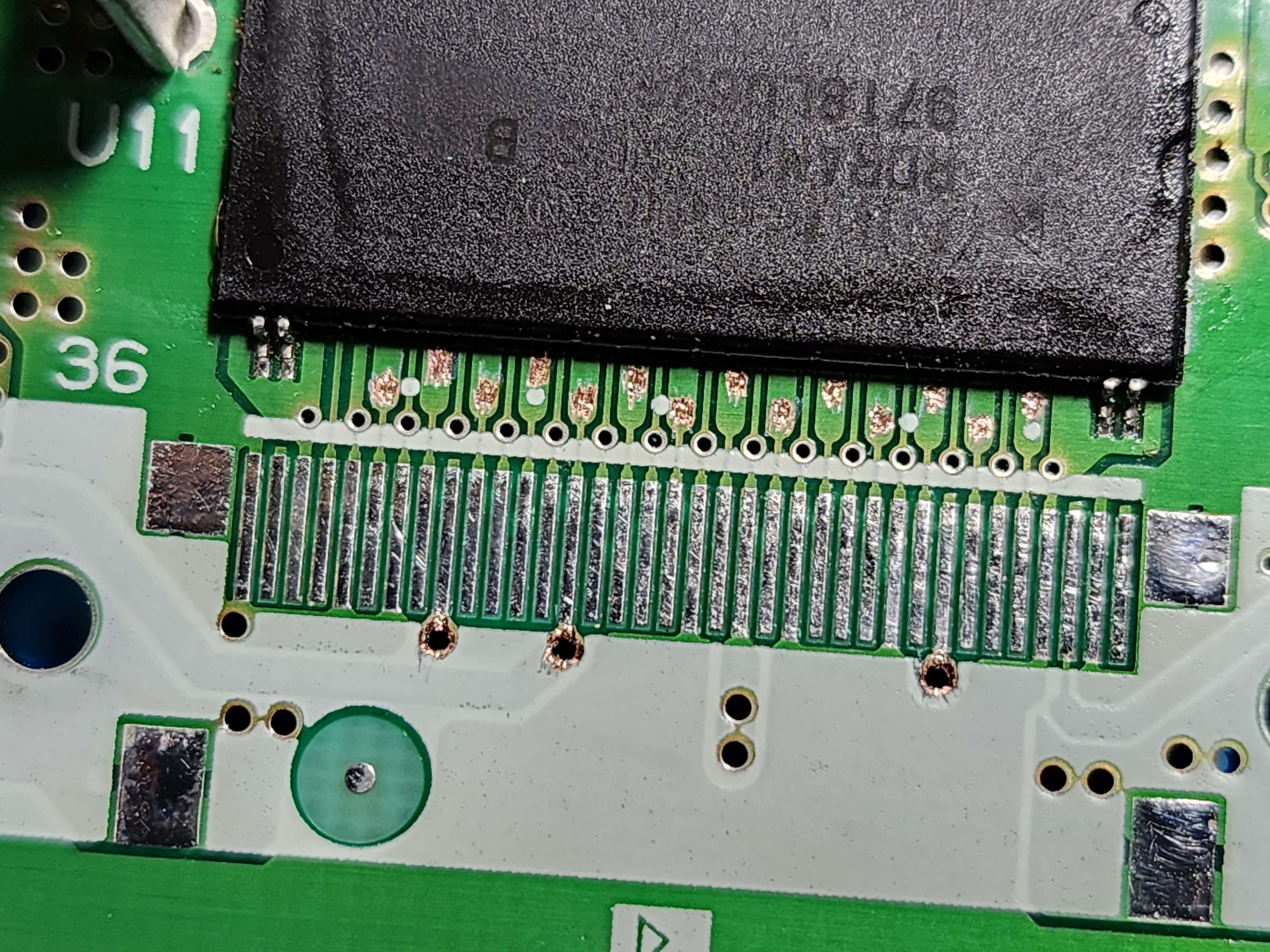
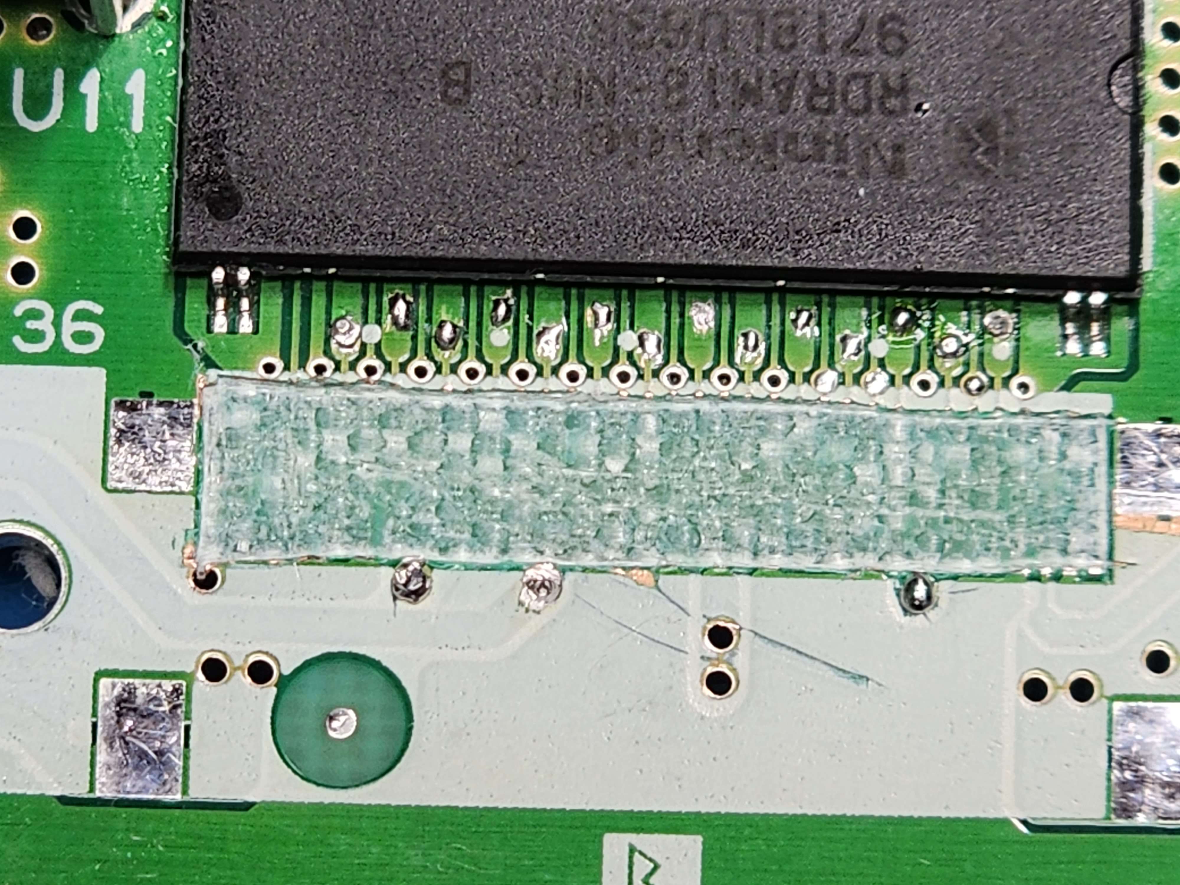
After waiting a FAT minute for them to arrive, I pulled the RAM expansion slot from one of my Test64s and, like a dingus, chose a 64 that doesn't have the rest points under the RAM chip (Rev 4 board). Oh well, nothing an xacto won't fix. I also scratched the VTerm and VRef vias.
Some curiosity surrounding this flex was if it would work without gouging out the original expansion slot traces like what's needed for the traditional Akira method. I left them in tact, popped the flex on and soldered on the caps and RAs (which can either be pulled from an existing jumper / expansion pak or bought brand new).
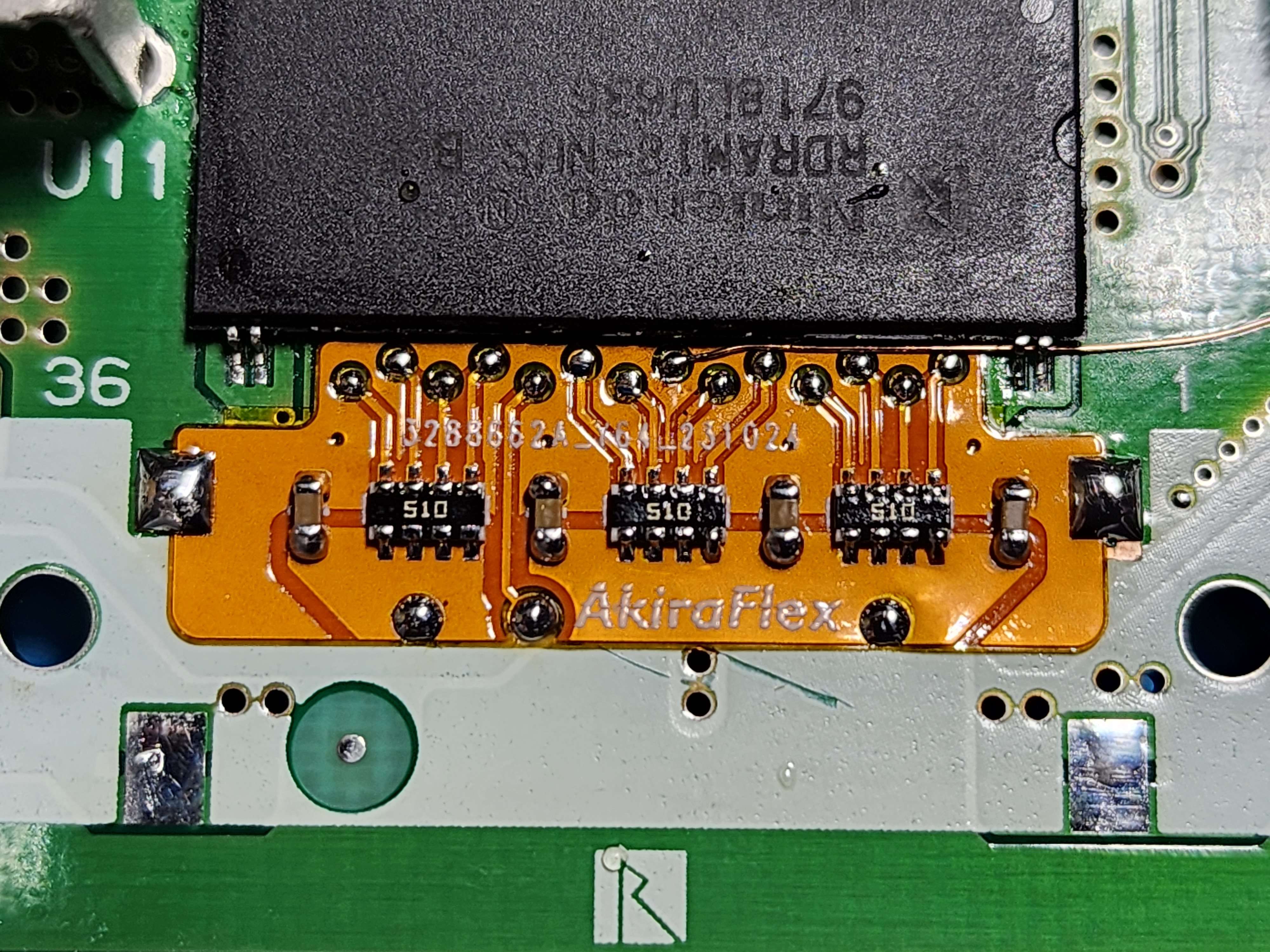
Popped a game in, powered it on, and like all good first tests, it did not work! I checked all my connections, reflowed all my joints, nothing I did seemed to work. I figured it could have had to do with the original RAMBUS traces still being in tact, so I hot aired the flex off and gouged out the original traces. Something worth mentioning: these JLC flexes can seriously take a beating! This one took hot air and the RCP-FFC flex took a lot of reflows without any bubbling or delamination, I'm quite impressed!
Popped the flex back on, tried again and..... NOTHING! I was banging my head against the table trying to figure out what was wrong with this thing, until it dawned on me... I never rewired the clock input! One lone magnet wire later, and we're in business!
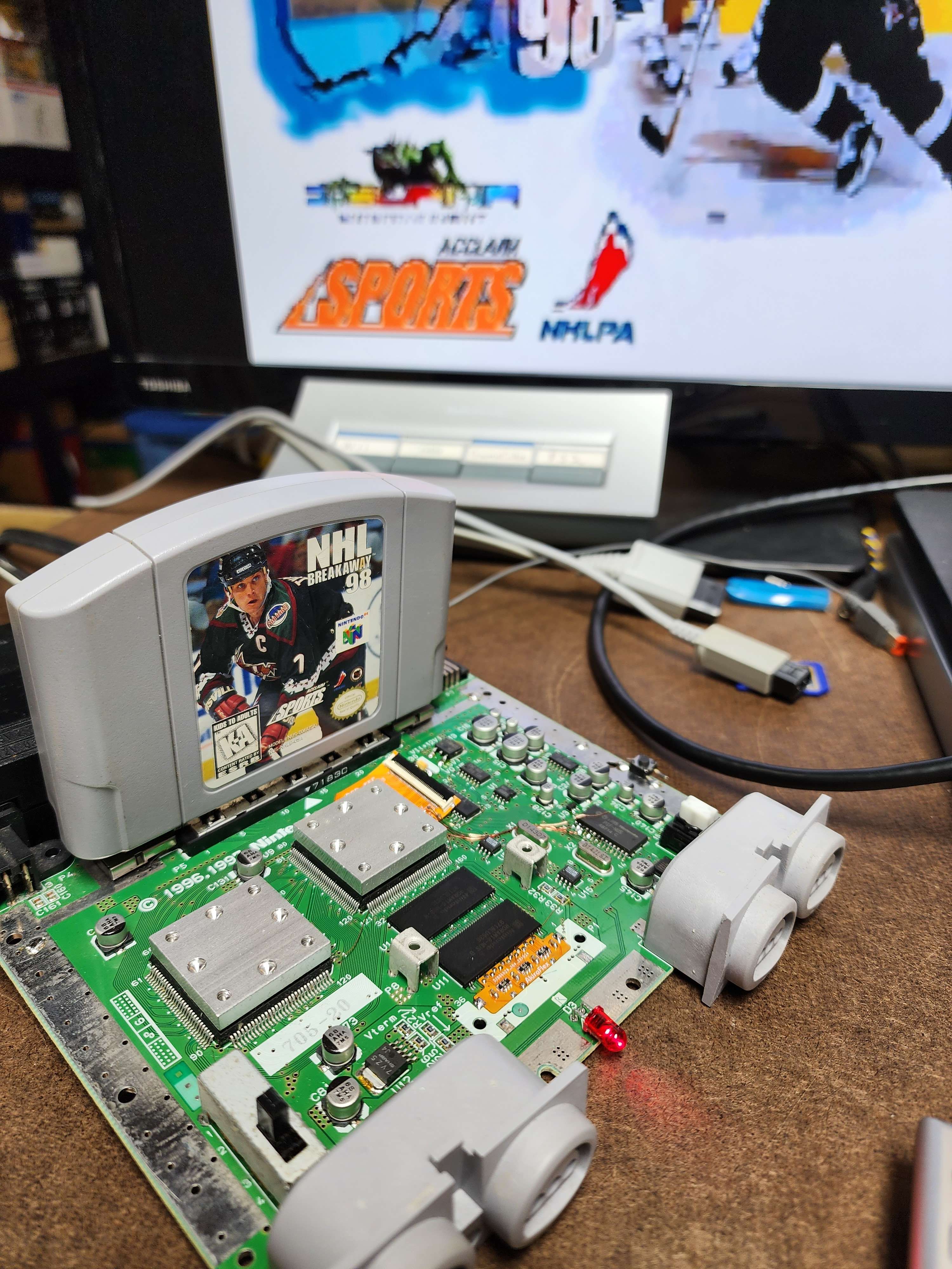
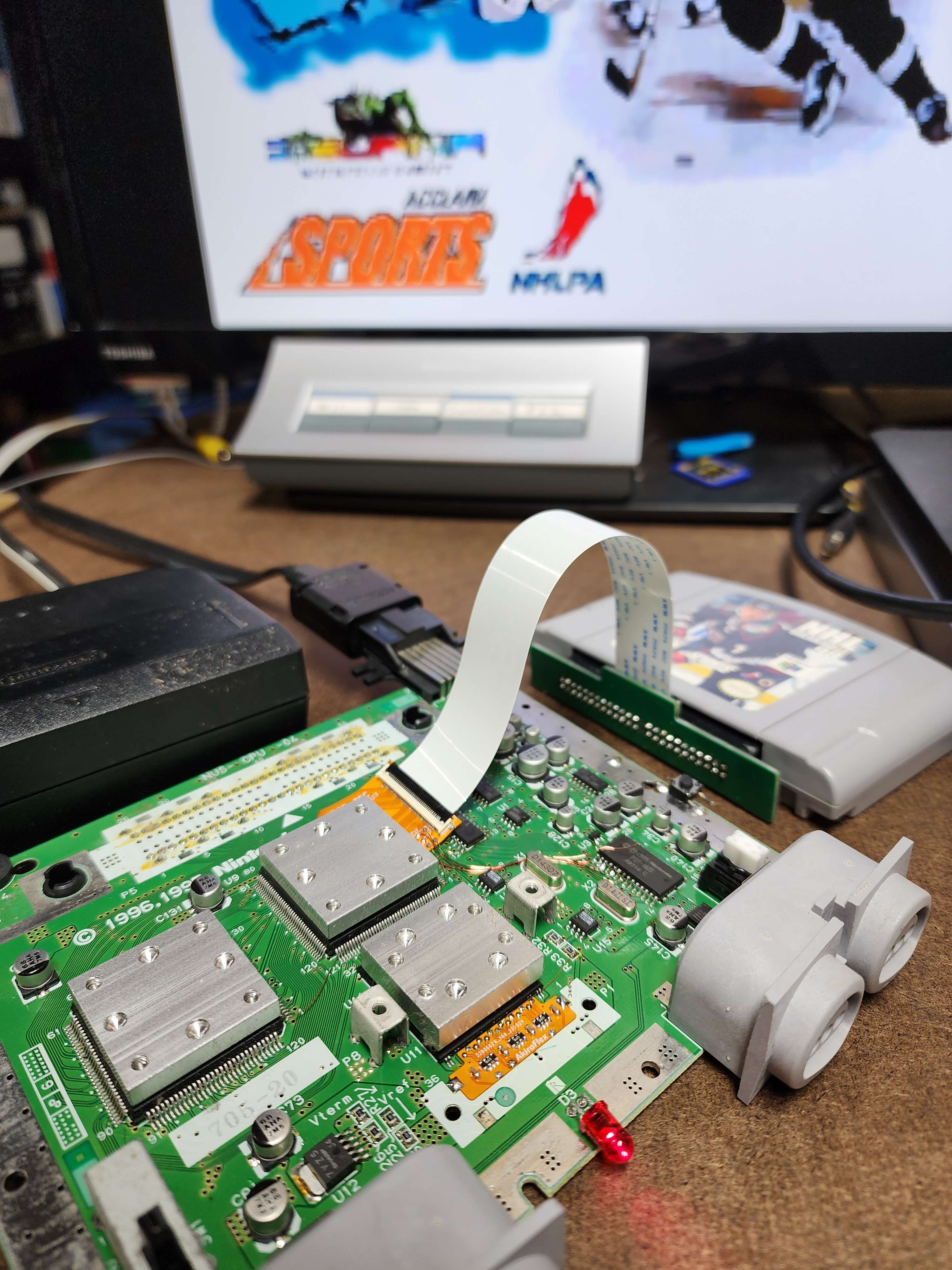
And with the RCP-FFC already being installed on this board, I just had to get this shot:
With all of this work done, I have to say that I do not plan on using this flex in my current build, being that the current Akira method seems to work just fine. For future builds though, this will make the process a lot easier. I do still need to test if the flex will work with the original expansion slot traces still in tact, as that still hasn't been properly tested.
As for what's next, I have been super inspired by the plethora of custom controller boards people have made over the years, especially with the recent showings from @cy and @Pears. I'm definitely going to borrow some design cues from Pears' board, integrating the majority of the buttons onto the main board, with FFCs for the joystick and D-Pad. Seriously clean work! I suppose I will need to have the controller layout in the front shell done first, so maybe that's the next step. Stay tuned!
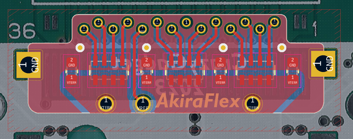
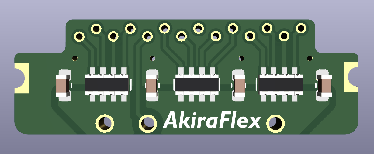
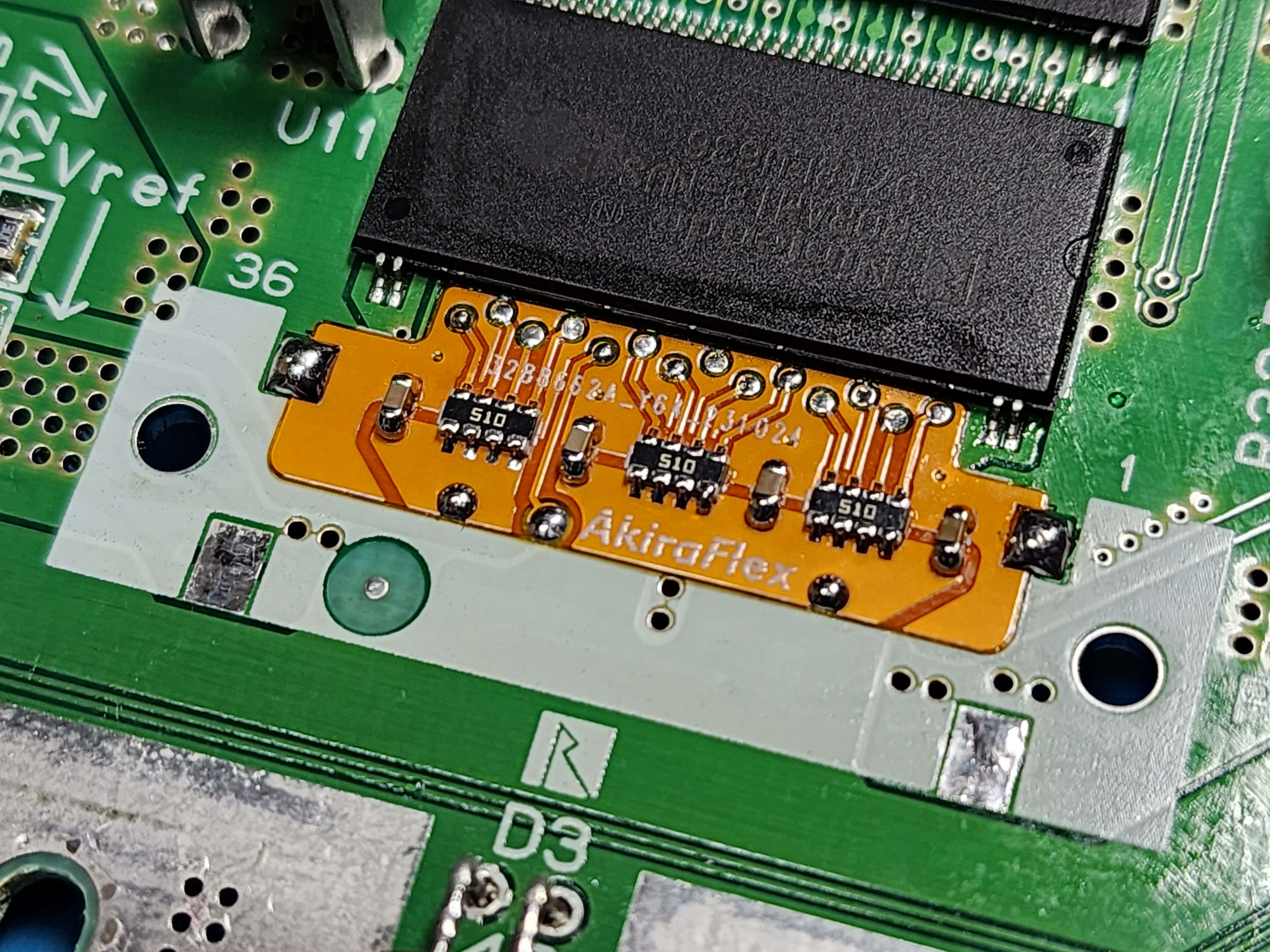
Before I started this project, I was reading through all the old worklogs I could find, and was very inspired by a lot of the design aspects of Noah's unfinished Fusion64 portable. Again, at the time, I had never made a flex PCB so the task seemed a bit daunting. After Shank suggested it, I made a new KiCAD project but didn't do anything with it, as I was focused on other things... After talking with @cy about his Terminator64 flex, I wanted to try my hand at a similar flex with a couple different design choices. Namely, I wanted mine to be almost completely wireless, soldering right to the test points under the bottom RAM chip on the N64, as well as pulling ground, VTerm and VRef from nearby pads / vias. Unfortunately, I would still have to manually wire the clock input, as there was no convenient via to pull it from. Taking inspiration from the original Akira method, I have dubbed this board AkiraFlex (how original!). Here's what it looks like:Looking great so far. Is there any technical reason why nobody has made a small rambus termination flex pcb? I've been wondering about a Terminator 64 for years.
Looking back, I could have run the traces a little differently so that the ground plane would run between all of them... something for the next rev (30 N64Ps later)!
After waiting a FAT minute for them to arrive, I pulled the RAM expansion slot from one of my Test64s and, like a dingus, chose a 64 that doesn't have the rest points under the RAM chip (Rev 4 board). Oh well, nothing an xacto won't fix. I also scratched the VTerm and VRef vias.
Some curiosity surrounding this flex was if it would work without gouging out the original expansion slot traces like what's needed for the traditional Akira method. I left them in tact, popped the flex on and soldered on the caps and RAs (which can either be pulled from an existing jumper / expansion pak or bought brand new).
Popped a game in, powered it on, and like all good first tests, it did not work! I checked all my connections, reflowed all my joints, nothing I did seemed to work. I figured it could have had to do with the original RAMBUS traces still being in tact, so I hot aired the flex off and gouged out the original traces. Something worth mentioning: these JLC flexes can seriously take a beating! This one took hot air and the RCP-FFC flex took a lot of reflows without any bubbling or delamination, I'm quite impressed!
Popped the flex back on, tried again and..... NOTHING! I was banging my head against the table trying to figure out what was wrong with this thing, until it dawned on me... I never rewired the clock input! One lone magnet wire later, and we're in business!
And with the RCP-FFC already being installed on this board, I just had to get this shot:
With all of this work done, I have to say that I do not plan on using this flex in my current build, being that the current Akira method seems to work just fine. For future builds though, this will make the process a lot easier. I do still need to test if the flex will work with the original expansion slot traces still in tact, as that still hasn't been properly tested.
As for what's next, I have been super inspired by the plethora of custom controller boards people have made over the years, especially with the recent showings from @cy and @Pears. I'm definitely going to borrow some design cues from Pears' board, integrating the majority of the buttons onto the main board, with FFCs for the joystick and D-Pad. Seriously clean work! I suppose I will need to have the controller layout in the front shell done first, so maybe that's the next step. Stay tuned!
Last edited:
cy
.
- Joined
- Sep 3, 2020
- Messages
- 116
- Likes
- 326
- Portables
- 6
That Akira flex really is clean and sexy man! The working trim you have is also beautiful as well! The cartridge slot is one of those things that CAN be relocated without too much difficulty at all, but the amount of magnet wire it adds really makes it a headache during and after the relocation since it's permanently attached. And that isn't even to mention the potential for one single wire to fail or pull loose... So with that said, the RCP flex is seriously one of the greatest things the N64 has seen in years just as yours and my jumper pak relocation flexes are!