Worklog Chimera GBA Emulator

Joined
Sep 18, 2022
Messages
19
Likes
29
Location
SP-BR
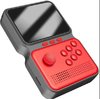
I got this console from a friend who bought it and didn't like the buttons. I tried playing on it, but the buttons are horrible, so that's how I started my first mod.

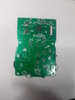
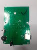
The original system is a Chinese emulator Gamebox M3 with hardware similar to the powkiddy v90, but with a very poor construction.
I only recently discovered that it is a board based on the SoC Allwinner F1C100s and that this board accepts the same firmware made by the community for the v90.

20221007_141557.jpg20221007_141544.jpgoriginal gamebox m3.jpg

I decided to use some dualshock parts I had at home and also bought a GBA shell and a Switch analogue.

gbashell1.jpg
gbashell2.jpg

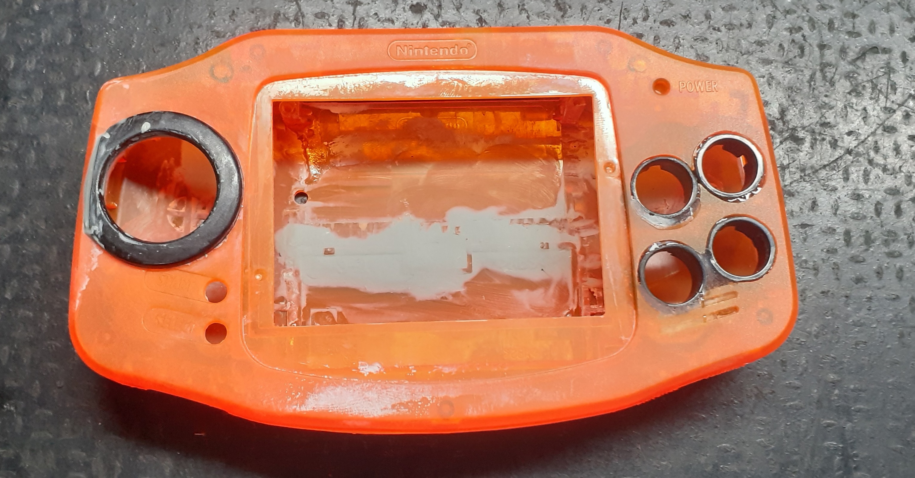
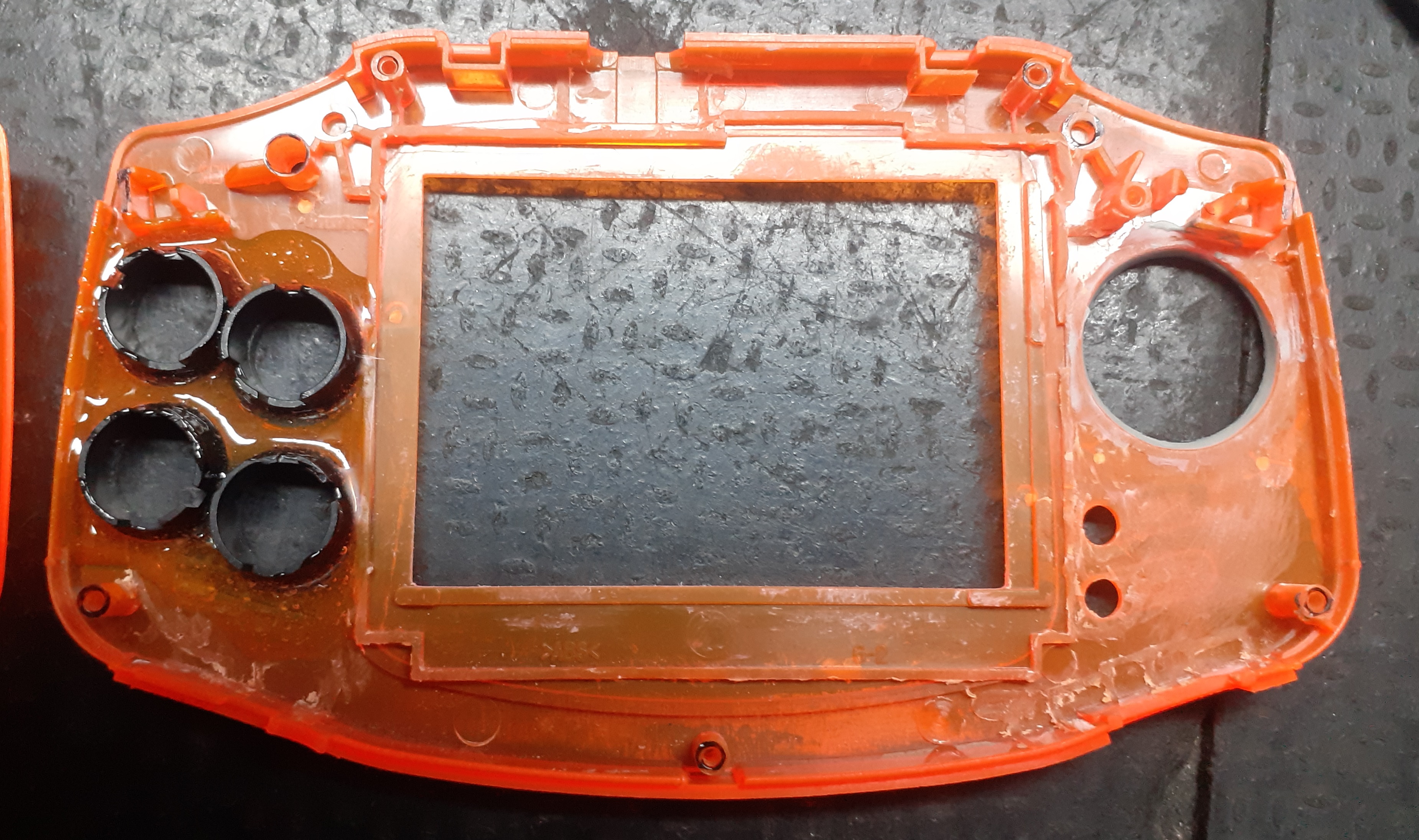
This is the initial result after a lot of dremel, epoxy putty and two-component epoxy glue and some sanding.

until later on...
 
Joined
Sep 18, 2022
Messages
19
Likes
29
Location
SP-BR
With the measurements of the board and case, I decided to just cut the board in half and fold it like a sandwich. After cutting, I spent many hours welding and measuring the continuity of the lines. For the analogue I used a connector taken from a notebook board, it's not the same size, but it worked.

082317.jpg
171502785.jpg

Here I'm testing the functions to find out if didn't fucked the board ;)
 

Rayden

.
Joined
Oct 12, 2023
Messages
4
Likes
0
English only
Me gustaría que hiciera un tutorial por favor quiero hacer lo mismo con una sup m3 que tengo gracias
 
Joined
Sep 18, 2022
Messages
19
Likes
29
Location
SP-BR
The next step was to make the boards for connecting the joystick and buttons.

To lower the cost of the project I decided to use scraps and home-made stuff with materials I already have.
joycon board-a.jpeg
joycon board-b.jpeg

I made this joystick breakout board with a prototype board and a connector taken from a notebook board.
The connector has more lanes than necessary, but it serves the purpose as it has the same distance
between pins as the joystick connector.


For the action buttons I used a similar process, but using parts of a board from an old dualshock

buttons board-a.jpeg
buttons board-b.jpeg

I know it looks ugly, but it works :oops:. After having the board ready I found out about the common ground in
these buttons, for now I'll leave it like that.
 
Joined
Sep 18, 2022
Messages
19
Likes
29
Location
SP-BR
Here is the result after a lot of sanding and filling to smooth the surface. I used a base coat of
general purpose spray primer, the second coat was black acrylic paint and then 3 coats of metallic
purple acrylic paint. To finish, I used 3 coats of spray varnish.

215748.jpg
748575.jpg

655230.jpg
221787.jpg


At these points marked in orange I placed a 3mm galvanized steel wire fixed with epoxy welding this gave the reinforcement
I needed in the case.
noname1.jpg


Where the cartridge socket was, I closed it with an ABS plate that was secured with epoxy welding.
Now here will be the volume potentiometer and the "home" button.
16.51.00.jpeg
 
Joined
Sep 18, 2022
Messages
19
Likes
29
Location
SP-BR
Here are some more detailed photos of this rat's nest!
15.42.50.jpeg
15.42.51.jpeg

16.51.00a.jpeg

22.10.15.jpeg

22.10.13.jpeg


This board does not have battery management so I am waiting for a tp4056 module to arrive which I will use here.
I intend to replace some cables there with thinner cables to save space, and then place a connector for headphones
and a rectangular cell phone speaker.
 
Joined
Sep 18, 2022
Messages
19
Likes
29
Location
SP-BR
Wow, there's very little left, I'm dying to see the final result
I plan to finish it next week during my vacation. At the moment I'm busy with my new resin printer and learning 3d modeling.
See you then and thanks for following along :)
 
Top