Worklog blueapple's portable wii

Joined
Oct 31, 2019
Messages
5
Likes
0
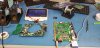
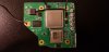
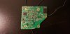
Hey everyone! I'm trying to build a portable Wii to play Gamecube games, but I'm running into issues when trimming the board and I need help. I'm reading low resistances when measuring across the 1.8V, 1.15V, and 1.0V nodes to ground. I've spent a while sanding the sides but I'm not making much progress in getting the resistance to change (aside from 3.3V). The Wii did power on properly with the U10 relocation before trimming. I attached some pictures below if that helps.

Resistances measured from V+ to GND:
  • 3.3V - 8.3kΩ
  • 1.8V - 38Ω
  • 1.15V - 53Ω
  • 1.0V - 12Ω

I also had some other questions about making a portable Wii:
  • Are the analog sensors for the L and R buttons required, or can I just use tactile switches?
  • Does anyone have any good heatsinks that work for the Wii? I was looking into getting a laptop heatsink, maybe one more common that could be bought for very cheap. I was looking at the Dell Lattitude D600 heatsink earlier.
  • I found these nice little buck converters that use a castellated PCB design so I can surface mount them onto a custom PCB. Anyone have any thoughts on these regulators?
  • Are there any USB PD modules to use with a 2S lithium battery pack? I saw someone mention a guy custom making them, but that's the only mention of one that I have seen.
20191214_124759.jpg 20191214_232404.jpg 20191214_232434.jpg
 

Timo43

.
Joined
Dec 7, 2019
Messages
55
Likes
14
Location
Subterranis, Danville, USA
Alright, so I’m not very qualified and tbh I don’t know the answers to some of these. However seeing no one else has replied I’ll try to help.

Low voltages: I’m no help here I’m still learning to build my portable.

Anolog buttons: no, you can use a dual tact mod or just tactile buttons. There is a tutorial for dual tact in the guide hub.

Buck converters: I think these would work but you might want to pm cheese or Aurelio to see.

Edit: To anyone reading this please post a question thread DON’T Pm someone to ask a question. (I was not aware of this when I posted)

Personally I would just buy a wii pms. It is about the same price as making your own pms and has nice features even if you don’t use all of them.

Heatsink: I would browse some work logs to see what people use for their type of build. There is no set standard (again, no experience so I don’t know if that Heatsink works.)

USB PD modules: not sure.

Sorry if I wasn’t that helpful but I hated no one attempting to respond to your questions. Good luck!
 
Last edited:

jefflongo

Broke BitBuilt
Staff member
.
.
Joined
Dec 15, 2016
Messages
1,017
Likes
1,361
Location
Santa Barbara, CA
Portables
3
Low resistance on the 1.8v and 1.15v is normal, provided they're above around 10 ohms. The 1v line seems pretty low though, you should probably continue sanding, increasing the grit as you go up to 600-1000. You can also use the Wii compendium as a guide to sand around the 1V area.

As stated above, many people use the dual tact mod for analog triggers. This is very easy if you're using a GC+.

Many people use a 35x35mm blower fan alongside a 35x35mm heatsink with a 35x70mm copper sheet to join the two. You can check out some other people's worklogs for that in action. A laptop heatpipe could be possible, but it's not really recommended to not use a fan without an extremely custom design.

Those buck converters could work, the spec states that they should be able to sustain a high enough current output. Of course there are other factors such as can these handle a sustained high current load and their thermal characteristics as I haven't seen anyone use these before. Many people have designed boards around the TLV62130 regulator, although it uses a 3x3mm QFN package so assembly might be harder. They do come in a small overall package and are quite reliable from my experience. Alternatively you can check out the Wii PMS (which is currently out of stock but should be restocked in January) which is a predesigned and assembled complete regulator and battery management solution in the BitBuilt store (it uses the regulators I mentioned).

Please don't go messaging specific people in the forums as stated in the above message regarding regulators. We suggest posting on the forums so more people have the opportunity to help and also learn from the responses in the public forum. Spread the knowledge!

The Wii PMS board supports it's companion USB PD charging board if you get it from the store. Otherwise, you'd probably need to seek a custom solution. Generally, the battery management is part of the regulator board if you're making your own design, and the USB PD is part of its own design to deal with the handshaking.

Let me know if you have any more questions!
 
Joined
Oct 31, 2019
Messages
5
Likes
0
Update:
I actually got the trimmed motherboard working! This time I was at home so I had to MacGyver a little power supply setup using another Wii which somehow actually worked. The sanding helped, but the U10 IC is really weird and is causing issues. I suspect that something isn't done properly with the relocation. Maybe I used U9 instead? I don't know. This sounds really stupid to me, and I don't have an explanation for why it behaves this way, but whenever I turn on the Wii, it will not boot until I load down the pin of U10 that has the magnet wire connecting to it. It can be anything, simply measuring the voltage on that pin with my voltmeter is enough to cause the GPU to notice that something has changed and it starts to display the PortablizeMii menu after a second or two. I took a video of it just so you guys can see how bizarre this actually is. I also got my hands on two 4 layer Wiis, so I will be able to start from scratch and be able to ignore the whole issue with the U10 IC acting all strange.

Power Regulation:
I actually bought a PICkit V4 about a week ago to make a GC+ (I'll definitely look into the dual tactile switches mod). It came in today and it looks pretty nice. It seems like the Wii PMS also uses a PIC microcontroller, so I can also make my own Wii PMS. I think right now my plan is to converge all of my circuitry onto one PCB. I can eliminate the 1.8V portion of the board and maybe even implement the USB PD Module as well. I'll have to see how difficult it'll make things for me. I have access to a PCB oven and some nice soldering irons, so I can make one fairly easily.

Heat Dissipation:
It was my intention from the start to use the heatsink I mentioned paired with a fan, I'm definitely going to look into other worklogs for ideas on heat dissipation. I saw one that used an ultrabook heat pipe and a blower fan, so I'm going look into some more modern laptop heatsinks because they probably are a bit more low profile.

To conclude this post, I have only one question:
  • Are the PCB files, .hex code, and BOM for the USB-C PD Charging + Internal USB Drive open source like the Wii PMS? I couldn't find anything with a couple of searches. I'd love to implement that design with the Wii PMS on one PCB.
 

jefflongo

Broke BitBuilt
Staff member
.
.
Joined
Dec 15, 2016
Messages
1,017
Likes
1,361
Location
Santa Barbara, CA
Portables
3
Update:
I actually got the trimmed motherboard working! This time I was at home so I had to MacGyver a little power supply setup using another Wii which somehow actually worked. The sanding helped, but the U10 IC is really weird and is causing issues. I suspect that something isn't done properly with the relocation. Maybe I used U9 instead? I don't know. This sounds really stupid to me, and I don't have an explanation for why it behaves this way, but whenever I turn on the Wii, it will not boot until I load down the pin of U10 that has the magnet wire connecting to it. It can be anything, simply measuring the voltage on that pin with my voltmeter is enough to cause the GPU to notice that something has changed and it starts to display the PortablizeMii menu after a second or two. I took a video of it just so you guys can see how bizarre this actually is. I also got my hands on two 4 layer Wiis, so I will be able to start from scratch and be able to ignore the whole issue with the U10 IC acting all strange.

Power Regulation:
I actually bought a PICkit V4 about a week ago to make a GC+ (I'll definitely look into the dual tactile switches mod). It came in today and it looks pretty nice. It seems like the Wii PMS also uses a PIC microcontroller, so I can also make my own Wii PMS. I think right now my plan is to converge all of my circuitry onto one PCB. I can eliminate the 1.8V portion of the board and maybe even implement the USB PD Module as well. I'll have to see how difficult it'll make things for me. I have access to a PCB oven and some nice soldering irons, so I can make one fairly easily.

Heat Dissipation:
It was my intention from the start to use the heatsink I mentioned paired with a fan, I'm definitely going to look into other worklogs for ideas on heat dissipation. I saw one that used an ultrabook heat pipe and a blower fan, so I'm going look into some more modern laptop heatsinks because they probably are a bit more low profile.

To conclude this post, I have only one question:
  • Are the PCB files, .hex code, and BOM for the USB-C PD Charging + Internal USB Drive open source like the Wii PMS? I couldn't find anything with a couple of searches. I'd love to implement that design with the Wii PMS on one PCB.
U10 and U9 are the same ic, it doesn't matter which one you use. Check the U10 troubleshooting guide. The USB PD board is not open source, however if you check Gman's website he has some information about the implementation. The USB C controller is STUSB4500. Unless you care about having an internal USB drive like the USB PD board in the store offers it's a relatively simple circuit to implement. Somewhere ST has a minimum design circuit that's even easier to implement then what's on the datasheet for the part. It's not too hard to find if you look for it.
 
Top