void
.
- Joined
- Jan 8, 2022
- Messages
- 40
- Likes
- 1
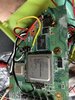
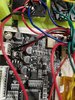
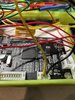
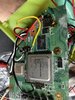
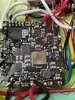
Hi, I was working on my g wii and the composite worked before, when trying to put it together the composite does not work anymore.
Attachments
-
 4.1 MB Views: 98
 -
 3.5 MB Views: 96
 -
 3.6 MB Views: 91
 -
 2.1 MB Views: 85
 -
 2.1 MB Views: 94
 -
 3.6 MB Views: 89
 -
 2.3 MB Views: 99
 -
 2.8 MB Views: 91
")