Worklog Baby's First GameCube Controller

Joined
May 11, 2021
Messages
24
Likes
13
Location
Somewhere on this Earth...
Portables
e^(i x π) + 0!
After discovering that Ginger would flame me if I ever made a GameCube portable, I have decided to put my GameCube portable project to the side. As much as I LOVE the idea of a Wii portable, I think I should take a step back and look at the bigger picture. So let's take a look at the controller.

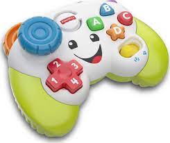
As much as I love the design of the GameCube controller, it's a bit too... serious for my liking. I think it needs a makeover. So, that's why I'm making a GameCube controller... out of the Fisher-Price Laugh and Learn controller.
download.jpeg


P.S: When this is finished, should I bring this to a Smash tournament? That would be quite a surprise to the people in attendance.
 
Joined
May 11, 2021
Messages
24
Likes
13
Location
Somewhere on this Earth...
Portables
e^(i x π) + 0!
This is the general idea of this project: Take a Fisher-Price Controller, and take a GC+2.0, and wire everything up to make it into an ACTUAL GameCube controller. There's only a few problems that might arise after doing some research and messing with it myself.
1) The joystick module that I'm planning on using is a BIT too big to fit in the shell, even WITH modifications. The board will actually have to be trimmed slightly to fit.
2) The joystick also has a pin that uses a "click down" button. As far as I know, there is NOT a pad on the GC+2.0 that tracks that. (PLEASE don't tell me that means I have to edit the GC+2.0's code :()

Also, I forgot to mention, my end goal is to have it so this controller still have ALL of the sounds and lights that it originally comes with. I just think it would be funny if you're shmovin' in Melee and the controller is screaming "TRIANGLE!" the whole time. I think this might make it so I have to shove an Arduino Pro Micro in there too. (I wanna mute the sounds on command if I want to, and I don't think the GC+2.0 can do that on it's own.

Feel free to correct me on anything I might have gotten wrong here. Thanks!
 

Stitches

2 and a Half Dollarydoos
Staff member
.
.
Joined
Feb 5, 2017
Messages
3,848
Likes
3,025
Location
Banana Bender Land, Australia
Portables
6
The GC+ indeed does not have a L3/R3 function, because the Wii/Gamecube don't have those either and cannot be made to recognise them. You can use a joystick that has it and just not wire it up tho
 
Joined
May 11, 2021
Messages
24
Likes
13
Location
Somewhere on this Earth...
Portables
e^(i x π) + 0!
The problem is, I want ALL of the original sound effects, and one of the sound effects on the controller is triggered when you click the joystick in. I COULD just wire up the click to an Arduino and have it activate the code from there?
 
Joined
Mar 20, 2023
Messages
41
Likes
26
Location
'Murica
The problem is, I want ALL of the original sound effects, and one of the sound effects on the controller is triggered when you click the joystick in. I COULD just wire up the click to an Arduino and have it activate the code from there?
Not sure what you mean, but you can actually use an Arduino to make a GC controller.
If you just want a sound effect, you can possibly wire the tactile switch to an Arduino's digital input and have the Arduino play a PCM sample with a piezo. I would also like a bit of clarification on what you wanna do here since I'm not really getting it lol.
 
Last edited:
Joined
May 11, 2021
Messages
24
Likes
13
Location
Somewhere on this Earth...
Portables
e^(i x π) + 0!
Sorry, my bad for being so cryptic, lol.

The controller board has sound effects whenever you click certain buttons on the controller, including when you click the joystick in. This is done by a pushbutton switch (I believe). When the switch is clicked in, the controller lights up and plays a short song. I want it to continue to play this song when modded, even if it essentially doesn't do anything on the controller.

I BELIEVE that I don't even need an Arduino inside now that I think about it. The switch is connected to the board with a two-pin connector, being Power and Ground. If I wired it up so the Power wire is connected to the "click" contact on the joystick module, and Ground to a Ground point, it SHOULD play the sound effect and light up when pressed, even if nothing happens controller-wise. Please correct me if I'm wrong though.

Again, sorry for not explaining it better, haha
 
Joined
Mar 20, 2023
Messages
41
Likes
26
Location
'Murica
Ah okay, in that case you should theoritically just run wires from the switches (metal dome or tactile or rubber contact?) and connect them to the GC+ or arduino or whatever. As long as the board is supplied power and has it's connection to the switches, then it should function as well.
 

Stitches

2 and a Half Dollarydoos
Staff member
.
.
Joined
Feb 5, 2017
Messages
3,848
Likes
3,025
Location
Banana Bender Land, Australia
Portables
6
Actually now that I think about it, you should check the logic voltage for the GC+ and the Fisher Price controller before you wire anything up. If they don't match up, then connecting any buttons to both the GC+ and the Fisher Price board could cause one's logic voltage to damage the other.
 
Joined
May 11, 2021
Messages
24
Likes
13
Location
Somewhere on this Earth...
Portables
e^(i x π) + 0!
It seems as if the Fisher-Price controller takes 3.3V. I could be wrong, but I found a website that converts this into a USB Game Controller. Quote: "The controller normally runs on 3 AA batteries (4.5V). As the batteries discharge, the voltage supplied gradually decreases. In fact, it will even continue to operate with just a jumper wire and 2 AA batteries (3V)."

Side Note, but this website (adafruit.com) has a lot of useful info, including how to mute the speaker. This will be useful.

Here is what the motherboard looks like:

Fisher-Price Board.png

Again, I have little to no idea what I'm doing, so correct me if I'm wrong (Please.)
 
Joined
Mar 20, 2023
Messages
41
Likes
26
Location
'Murica
I really assumed the PCB would look like that, an FR2 (or looks like it) PCB with a large COB in the middle lol. Anyway, it seems like all the button traces have exposed pads to conveniently solder jumpers to. As such as long as you provide the 3.3v to the board and solder the wires to your GC+ or Arduino it should in theory work. I saw a disassembly video on this and noticed that the joystick isn't actually a joystick, it just has a pressure sensitive button on the bottom that triggers a noise when you press it. It's connected to the back of the board using a JST connector or something, as well as the speaker. If you want to actually use the joystick, you will have to mod in a real stick box (if there's enough space).
 

Stitches

2 and a Half Dollarydoos
Staff member
.
.
Joined
Feb 5, 2017
Messages
3,848
Likes
3,025
Location
Banana Bender Land, Australia
Portables
6
Running it off the same 3.3v feed as the GC+ should be safe then
 
Top