Worklog Ashida, My first wii portable

Joined
Oct 27, 2023
Messages
15
Likes
27
Location
Vancouver, Canada
Portables
2
Hi all!

I've been lurking on and off around Bitbuild for a couple of years now and finally got the courage to start my first portable. I'm super new to soldering and all things electrical. The max I did before this was swap out a couple of Gameboy and PSP shells. I started practicing soldering last month to do my first Ashida build.

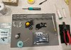
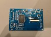
Prior to this I had no tools so I order them plus wires along with the 4layer bords and parts from digikey. I got all the links form the BOM.

With that out of the way time for some worklog updates.

Wii trim
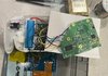
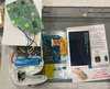
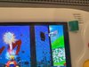
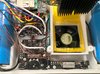
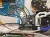
I got an old wii from ebay and ran through the soft modding procedures. Then I began disassembling it and prepped for the trim.
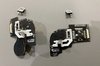
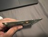
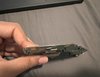
I followed along GingerOfVODs and Dubesinhower youtube videos for this part and after a lot of adrenaline jitters I was finally able to get through the trim. I also plan to add the MX chip if things go well so I trimmed that as well.
a_trim_01.JPG a_trim_02.JPG a_trim_03.JPG

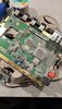
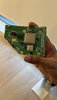
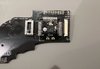
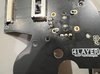
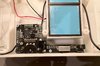
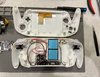
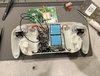
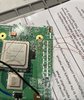
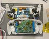
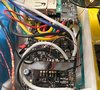
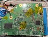
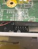
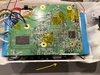
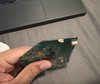
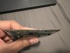
Next step was sanding down the corners. I started with 300 grit and made my way up to 1000 grit. This is what the trimmed wii looks like.
b_sanding_01.jpg b_sanding_02.jpg b_sanding_03.jpg b_sanding_04.jpg b_sanding_05.jpg b_sanding_06.jpg

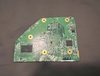
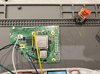
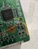
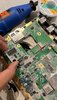
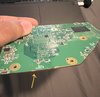
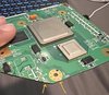
I noticed a few places where I nicked the board with my dremel. Would this cause issues?
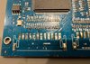
c_sanding_query_01.jpg c_sanding_query_02.jpg

Trim resistance
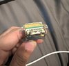
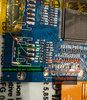
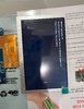
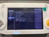
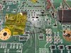
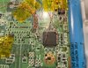
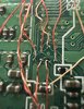
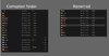
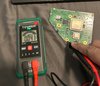
This is what my resistances look like after I sanded my trimmed board.

d_trim_resistance.jpg


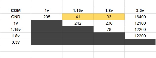
I do have a query in this section. I have a Tesmen TM-510 multimeter that displays in Kohms and has no manual control to switch between resistance and continuity mode.

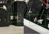
What I noticed was that GND - 1.15v & GND - 1.8v (highlited in yellow) shows continuity. Is this something I need to fix? or is the resistance too low for my multimeter to measure & is causing it to show continuity?

e_GND-115v.jpg

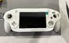
Thats it for now. I will update soon as soon I get my shell from PCB way and 4layer boards. Thanks and gave a great day/night!
 

CrazyGadget

Crazy Helpful, CrazyGadget
.
.
Joined
Jun 6, 2020
Messages
622
Likes
920
Location
Downing's Closet
Portables
???
That trim and your resistances look good! Most multimeters will beep for continuity for anything below 50(ish) ohms, but we're really looking for dead shorts (0 ohms) with our checks. It's normal for those lines to have that low of resistances. For future trims, I would recommend starting with even lower grit sandpaper (I like to do 80, 180, 220, 320, 400, 600, 800, 1000). Since this trim is checking out fine though, I don't think a resanding is necessary.

Great work so far!
 
Joined
Oct 27, 2023
Messages
15
Likes
27
Location
Vancouver, Canada
Portables
2
That trim and your resistances look good! Most multimeters will beep for continuity for anything below 50(ish) ohms, but we're really looking for dead shorts (0 ohms) with our checks. It's normal for those lines to have that low of resistances. For future trims, I would recommend starting with even lower grit sandpaper (I like to do 80, 180, 220, 320, 400, 600, 800, 1000). Since this trim is checking out fine though, I don't think a resanding is necessary.

Great work so far!
Awesome! Thank you CrazyGadget for explaining the resistances and continuity. That makes a lot of sense now. I'll also keep the lower grit sandpaper in mind for any future trims. :)
 
Joined
Oct 27, 2023
Messages
15
Likes
27
Location
Vancouver, Canada
Portables
2
Hello everyone. Its time for another update. :) Spoiler alert, my trimmed wii is ALIVE!!

I ran into a couple of beginner mistakes which I was well aware of and tried to avoid as mush as possible, but my eagerness got the better of me. I would like to reiterate for any beginners like me reading through posts, Listen to the advice given here! don't rush things and be patient. Always test as you go!

4Layer pcbs and battery
Once I had all the 4layer pcbs and battery in my possessions, I was finally ready to start my build. I started off with the controller pcbs and soldering all of its components. My thought process was to start with the "simple" stuff and build up my soldering confidence for the trimmed wii and PMS2. I also decided to solder the speakers. For the most part I used 34awg magnet wires.

f_controller_solder_00.jpg f_controller_solder_01.jpg f_controller_solder_02.jpg f_controller_solder_03.jpg

Screen Driver board
I was slowly getting comfortable with soldering and decided to tackle the driver board next. I went over the 3.3v and also remove the connector pins. My strategy was to add a lot of solder to the joints and slowly lift up one side and make my way to the other. It did work for the most part. This is where I made Mistake #1.

The smaller connectors came off relatively easy but I was struggling with the large one. I was starting to get a bit frustrated and In the heat of the movement I grabbed a metal prying tool to stick it under the connector to help lift the pins. I noticed that I was scratching the board and realized I might end up damaging the traces so I quickly backed off.
It took a lot of patience and solder but I was finally able to remove the connector. I did end up damaging/lifting a pad underneath. Luckily it was the SDA/SCL pads. I believe we don't need those.
I cleaned up the excess flux, solder and give the board a nice ipa bath. This is what it looks like. I was worried about the scratched traces at this point though but it works fine.

g_display_board_01.jpg g_display_board_02.jpg g_display_board_03.jpg

Trim Test #1
Now I was getting pretty comfortable with solder and was eager to fit everything into the 3d printed shell. I started off with the interface board and next was the screen and left controller.
h_trim_test1_01.jpg h_trim_test1_02.jpg h_trim_test1_03.jpg

I didn't have a spare battery connector so I decided to screw in the pms2 to the shell and have longer voltage wires hooked up to the wii for testing. Naturally this was a bit difficult since I was not used to soldering in tight spots. It was an ok first attempt but I learned a lot and had to redo the connections several times. Also if anyone is reading, please tin your voltage wires before soldering them to the pms. My wires would break off randomly because of this and could potentially save you a lot of troubleshooting in the future.

h_trim_test1_04.jpg h_trim_test1_05.jpg

I ripped off the video connector along with a bit of wii motherboard and tried to salvage what was left. I hooked it all up to my TV and tried to boot the trimmed wii. The wii would get warm and the fans would turn on but my TV didnt pick up any signal. It was probably because I damaged the connector with my dremel and could'nt desolder the board completely.

h_trim_test1_06.jpg

At this point I was maybe getting a bit overconfident and shrugged it off and decided to hook up the VGA lines to the screen. This was Mistake #2.
I knew I should have tested this first but I was too eager to see the final result. VGA was a lot harder then anticipated especially the H,V sync lines. They are really tiny.
I soldered my RGB connections to the solder points in the image and all of the ground signal wires to the large ground screw post. This did not work.

h_trim_test1_07.jpg

Is the ground connections different for voltage and display?

I tried to re-solder all my connections and checked U10 and MODE voltages as well. I realized that things were starting to get out of hand and I had to step back and get back to testing my trim rather then wrestling all the magnet wire connects I had.

I ended up completely undoing all of the voltage wiring, desoldering the half cut components at the edges and went over a sanding pass starting with 80 and made my way up to 1000 grit sandpaper and gave the trim a nice good ipa bath. I did twice just in case. I also re-checked my resistances at this point.

I highly suggest anyone struggling with a black screen trims to watch this video by Ginger. This was very very helpful! Thanks Ginger.

Trim Test #2
After all that I finally came to a conclusion that testing composite was the way to go and there is a reason why everyone suggests it. It was 2 straightforward connections. I was also not very confident with the ripped out video connector so I had to make a few connections and attach a button to the Display driver board to switch to AV.

If anyone is stuck here, I found this forum post.

i_trim_test2_02.jpg

I also moved my composite wires to a via below C57 and ground to TP50. This was from Dubesinhower guide . After all of that I was finally ready to test again.

i_trim_test2_03.jpg i_trim_test2_01.jpg

I put the batteries after double checking all my connections aand It WORKS!!....for now atleast

i_trim_test2_04.jpg i_trim_test2_05.jpg

I still cant wrap my head around the things I had to do to the wii motherboard and it still survived! This is all thanks to the tremendous effort of everyone here. Thank you all!

Next step is USB wiring. Thanks and have a great day/night!
 
Last edited:
Joined
Oct 27, 2023
Messages
15
Likes
27
Location
Vancouver, Canada
Portables
2
Hello! Hope you all had a great weekend!
I have a big update! I was able to get a lot done over the weekend and I almost have a fully working Ashida. :D

k_gametest_01.jpg

I did run into a few issues that I'm having difficulty with.

1. Audio
I have no audio output from the speaker or headphones. I did notice the volume animation going up/down when I rotate the potentiometer but the volume number stays fixed (65 in screenshot). I also plugged in headphones & the icon changes to headphones but no audio.

I checked connectivity and it seems fine between scw/sdw from the pms2 to interface board to the wii motherboard. I also checked continuity of MC C D WS from the interface to wii via's and to the AV chip itself.

k_audiotest_01.jpg k_audiotest_02.jpg k_component_status_01.jpg

A few pictures of the internal wiring

j_internals_01.jpg j_internals_03.jpg j_internals_02.jpg j_internals_mb_01.jpg j_internals_mb_02.jpg j_internals_mb_03.jpg

2. Controller buttons
The second issue I'm having is with my Dpad and L2 button. I guess I didn't do a good job soldering the ribbon cable connectors between the two controller boards. I'm thinking of removing the connectors and soldering 34awg magnet wires instead. Would this be wise?

j_internals_gc_01.jpg

And that is all for now. If you have any suggestions regarding the audio or controller buttons please let me know.

Thanks and have a good one!
 
Joined
Oct 27, 2023
Messages
15
Likes
27
Location
Vancouver, Canada
Portables
2
I have no audio from the speaker or headphones. Not even static. Any ideas what might be causing this?

Just to test, I played Wind Waker for about 30 mins and the following are my observations

1. Game works flawlessy. No glitches or visual artifacts. No sound.
2. L button was not working in the controller tester but works in game.
3. Ashida sometimes does not boot if I leave headphones connected and try to power it on.
4. I noticed the volume icon pop up a few times during gameplay but still no audio.

Things I tried so far
1. Shortened MC C D WS wires.
2. Re soldered joints on interface board
3. Checked continuity from interface board to pins on AV chip. Continuity seems ok.

I may have damaged the MC, D vias by scraping too much. I still get continuity from the vias to the AV and interface board though. But no audio.
l_audio_issue_02.jpg l_audio_issue_03.jpg

Update: I suspect I may have used excess solder when I did the 3.5 headphone jack. Could this be the source of my audio problems?
i_audio_issue_04.jpg
 
Last edited:
Joined
Oct 27, 2023
Messages
15
Likes
27
Location
Vancouver, Canada
Portables
2
Finally! I was able to fix the audio issue. It was a combination of the MC wire length and not soldering the ground wrapping wire properly.

The wire in the image is just a test. I re-did the wires properly and everything works great! Now time for some Wind Waker stress tests and on to the MX chip. I honestly didnt think I'd reach this far. :)

i_audio_issue_fixed.jpg
 
Joined
Oct 27, 2023
Messages
15
Likes
27
Location
Vancouver, Canada
Portables
2
Alright, One last update.

I did a lot of testing and my Ashida had surprisingly good connections. It used to boot 10:10 times and the usb/audio had no issues at all. I was super satisfied with the build and finally ready to tighten the screws. This is where things took a turn :(

I would have never guessed that tightening the screws was the hardest part! I was using the old screws from the wii disassembly and I guess the screws were too old so they started to strip easily. I had 3 stripped screws at one point and getting them out was a pain. I ended up breaking one of the screw posts and I guess I was tugging on a few wires while prying on the screwhead. Now the console is a bit unstable and boots maybe 5:10 times.

I've also had Wind Waker freeze while loading and corrupt the rvloader folder. I fixed this by renaming the folder & copying over a fresh one from the zip.
m_usb_corruption.jpg

This however does not take anything away from how awesome the whole experience has been! A few months back I had no idea how to solder or use a multimeter. Thank you all for the help and support!

I also beat Wind Waker on this Ashida. It was an amazing experience.

m_windwaker_test_01.jpg
 
Joined
Oct 5, 2019
Messages
132
Likes
122
Portables
2
Alright, One last update.

I did a lot of testing and my Ashida had surprisingly good connections. It used to boot 10:10 times and the usb/audio had no issues at all. I was super satisfied with the build and finally ready to tighten the screws. This is where things took a turn :(

I would have never guessed that tightening the screws was the hardest part! I was using the old screws from the wii disassembly and I guess the screws were too old so they started to strip easily. I had 3 stripped screws at one point and getting them out was a pain. I ended up breaking one of the screw posts and I guess I was tugging on a few wires while prying on the screwhead. Now the console is a bit unstable and boots maybe 5:10 times.

I've also had Wind Waker freeze while loading and corrupt the rvloader folder. I fixed this by renaming the folder & copying over a fresh one from the zip.
View attachment 30973

This however does not take anything away from how awesome the whole experience has been! A few months back I had no idea how to solder or use a multimeter. Thank you all for the help and support!

I also beat Wind Waker on this Ashida. It was an amazing experience.

View attachment 30974
Any luck on fixing the boot issue?
 
Joined
Oct 27, 2023
Messages
15
Likes
27
Location
Vancouver, Canada
Portables
2
Any luck on fixing the boot issue?
I was able to fix it to a reasonable amount. Its by no means a perfect boot but it takes me a couple of quick restart to get going. I also didn't want to re-do my wiring since I scraped a lot off of some of the vias and getting a solid connection was a nightmare.

Going through Gingers VODs and other forum resources, I've narrowed it down to USB wire length and wrapping tightness. On top of that what I noticed during my build was the VGA lines can cause interference if you have spaghetti wiring (which I did). Shortening wire length and organized wire routes helped a lot with this. Also avoid wires crossing over each other.
I had an issue where I did not solder one of my ground wrapping wires properly on the audio lines which decreased the overall boot stability.

Hope that helps.
 
Top