ApolloVI
.
- Joined
- Jul 3, 2023
- Messages
- 9
- Likes
- 4
Hello! I'm fairly late into the project I think, but I figured I would start a thread to answer a few questions I had.
What's done so far:
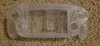
-All components ordered and received (except for the two little 3D printed buttons for the bottom edge, they were too small to order and I'm seeing if I can 3D print those at my local library )
)
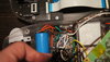
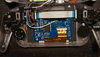
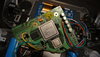
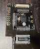
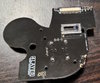
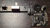
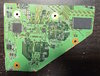
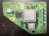
-Boards are populated and mounted in place in the shell. Even managed to do the FFC connectors with no bridging. Ready to be buttoned up once wiring is done.
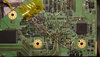
-Wii hacked with RVLoader, trimmed, sanded, LDO removed, cleaned, and resistances look good.
Currently working on:
-Wiring! I'm probably about 80% done I think. It's a bit of a WIP mess right now so I don't want to take a pic quite yet Following the 4Layer Ashida PCB diagram is pretty straightforward, but I had some questions below. I struggled with soldering to the vias on the Wii board, but then I realized my magnet wire might be a tad too thick at 32AWG. After getting some 36AWG it seems to be going much better. Just need a little bit of clarification before finishing the remainder and tidying things up.
Left to do:
-Testing and inevitable troubleshooting...
-If all goes well with the basics I'd like to trim and add the MX chip.
Questions:
1.So this is my main question, what wiring, exactly, needs to be done besides the wiring shown on the 4Layer Ashida PCB set diagrams and the RVL-PMS-2 diagrams? I know that wiring the screen driver board is a matter of following the directions on the back of the driver board for RGBHV to the correct vias on the Wii board based on the trim guide. ANYTHING else I should 100% be wiring before my first attempt at powering on?
(UPDATE: I've powered on and gotten signs of life, so I think I've cleared this "what do I need to get done" hurdle and I'm onto tweaks and troubleshooting. The answer to this question seems to be to triple check both of those pages. It's all there but it's easy to miss something. The wire for the U10 replacement pin is something I missed until very recently. A bigger question that I found was the ideal way to route the wires, but that was eventually figured out after much trial and error.)
2. Followup to that, assuming the above is correct, would that mean I ignore the individual wiring diagrams for U-Amp 2 and GC+ 2 since they are directly soldered to the Ashida PCBs?For example, I wouldn't need to wire the 3.3v pad and ground on the GC+ board to the PMS-2 since it's already soldered directly onto the controller board, right? The Ashida PCB set diagram ignores these pads on the GC+ which is why I ask. (Never mind, I think I figured out what these are for - providing a convenient place to wire 3.3v and ground to the screen driver. Still, general question remains whether I need to address anything on those individual diagrams for those two boards like the additional configuration jumpers on the U-Amp, but I think the answer is no)
3.How many "things" should be wired to 3.3v? By my count I should have Right Controller board, Interface Board, PMS-PD 2, the Wii motherboard, and the screen driver board all wired to 3.3v. Is that correct? What is the ideal way to wire all these? Can I daisy chain them? It wasn't really clear to me how people were doing it based on other builds. Dubesinhower's latest video has cleared this up for me. I wasn't crazy about thinking this was crowded. But I piled all my 3.3vs (except for the screen driver board as mentioned above) onto the same pad and initial tests seem to show that it works fine.
Thanks and I look forward to finishing!
August 11th, 2023 Update:
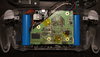
Will do a proper update with pics soon, but I've been slowly working on things here and there. I finished wiring, re-checked everything, tried to power on and didn't get anything. I was about to take pics and ask for help, but I re-organized and re-did some things, and finally today I got my first signs of life! I booted into Priiloader, and then after messing a bit with my data wires, got into RVLoader. A second big success is that I didn't bother with testing on composite and went straight for VGA out, and it's working (well, after the solder job on some of my wires came lose a few times).
What's done so far:
-All components ordered and received (except for the two little 3D printed buttons for the bottom edge, they were too small to order and I'm seeing if I can 3D print those at my local library
)-Boards are populated and mounted in place in the shell. Even managed to do the FFC connectors with no bridging. Ready to be buttoned up once wiring is done.
-Wii hacked with RVLoader, trimmed, sanded, LDO removed, cleaned, and resistances look good.
Currently working on:
-Wiring! I'm probably about 80% done I think. It's a bit of a WIP mess right now so I don't want to take a pic quite yet
Following the 4Layer Ashida PCB diagram is pretty straightforward, but I had some questions below. I struggled with soldering to the vias on the Wii board, but then I realized my magnet wire might be a tad too thick at 32AWG. After getting some 36AWG it seems to be going much better. Just need a little bit of clarification before finishing the remainder and tidying things up.Left to do:
-Testing and inevitable troubleshooting...
-If all goes well with the basics I'd like to trim and add the MX chip.
Questions:
1.
(UPDATE: I've powered on and gotten signs of life, so I think I've cleared this "what do I need to get done" hurdle and I'm onto tweaks and troubleshooting. The answer to this question seems to be to triple check both of those pages. It's all there but it's easy to miss something. The wire for the U10 replacement pin is something I missed until very recently. A bigger question that I found was the ideal way to route the wires, but that was eventually figured out after much trial and error.)
2. Followup to that, assuming the above is correct, would that mean I ignore the individual wiring diagrams for U-Amp 2 and GC+ 2 since they are directly soldered to the Ashida PCBs?
3.
Thanks and I look forward to finishing!
August 11th, 2023 Update:
Will do a proper update with pics soon, but I've been slowly working on things here and there. I finished wiring, re-checked everything, tried to power on and didn't get anything. I was about to take pics and ask for help, but I re-organized and re-did some things, and finally today I got my first signs of life! I booted into Priiloader, and then after messing a bit with my data wires, got into RVLoader. A second big success is that I didn't bother with testing on composite and went straight for VGA out, and it's working (well, after the solder job on some of my wires came lose a few times
).Attachments
-
 1.2 MB Views: 48
 -
 1 MB Views: 50
 -
 1.9 MB Views: 43
 -
 1.2 MB Views: 44
 -
 1.2 MB Views: 43
 -
 2.1 MB Views: 37
Last edited: