
- Joined
- Oct 5, 2019
- Messages
- 132
- Likes
- 122
- Portables
- 2
Over the past month I've been gathering together the things I need to do an N64 build. I am finally ready to start a worklog now that I have most of the necessary parts. I wanted to start with what I have done so far up to this point. This post might be a little scrambled and all over the place, hopefully it serves as a good update.
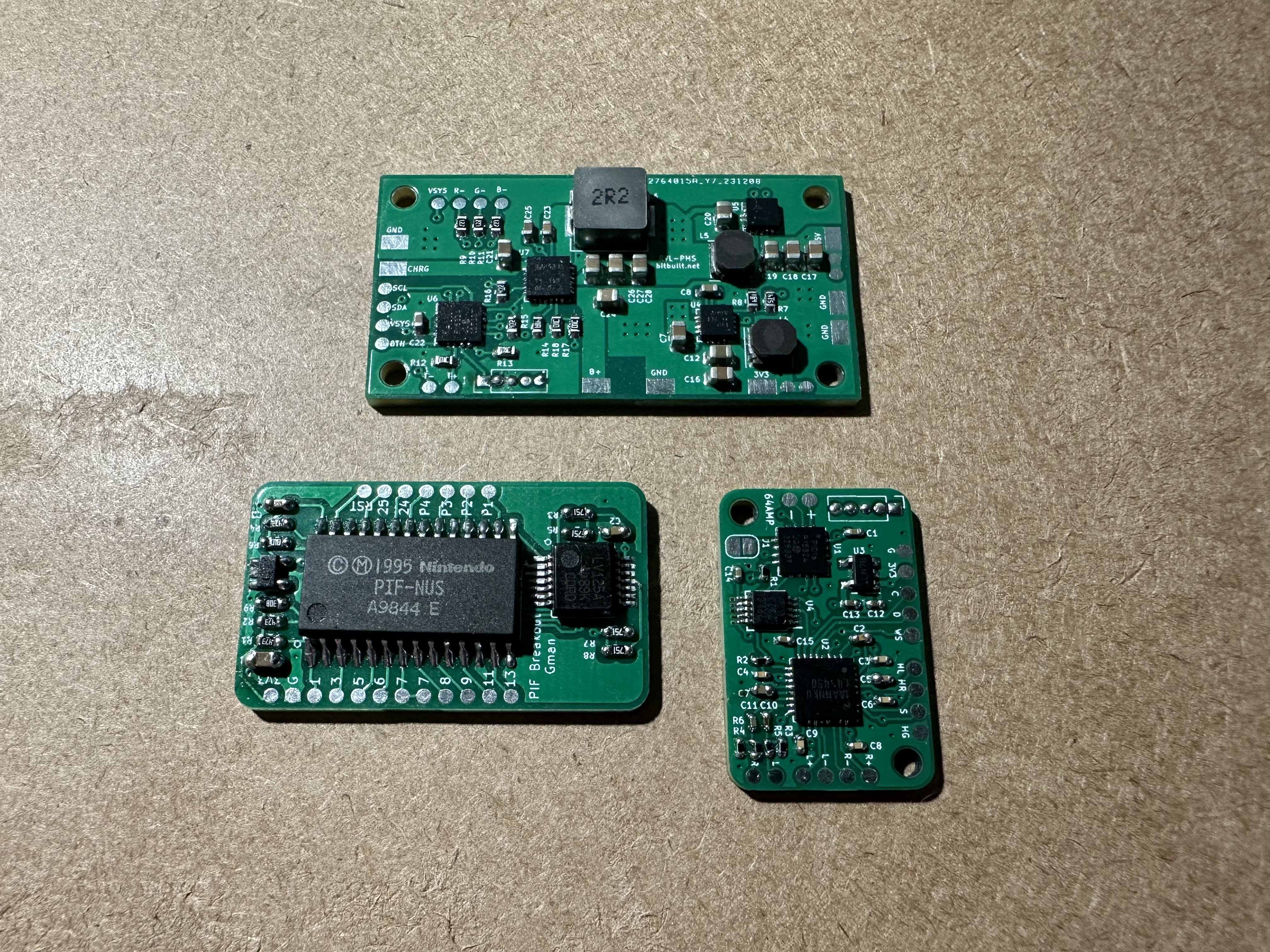
I first started with the main open source boards for the N64. I knew I would need the RVL-PMS, N64 Amp, and PIF relocations boards.
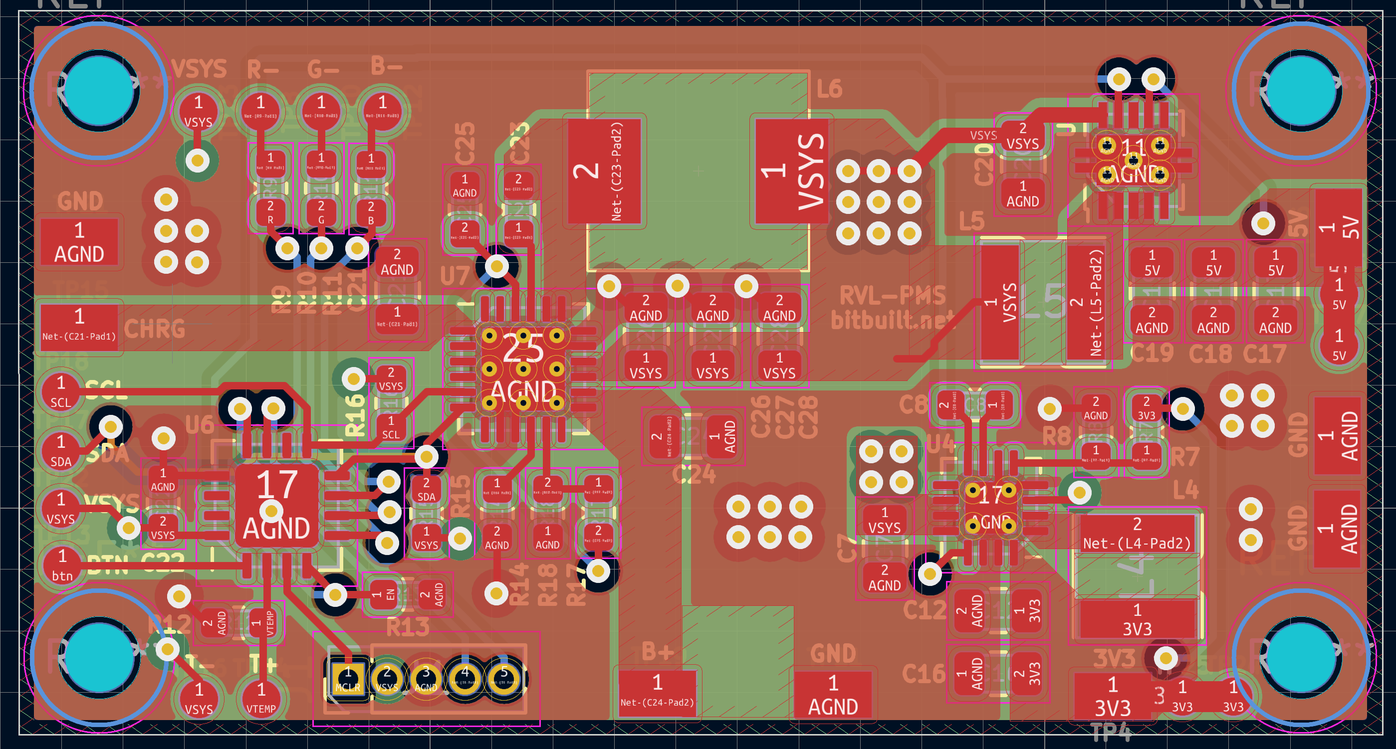
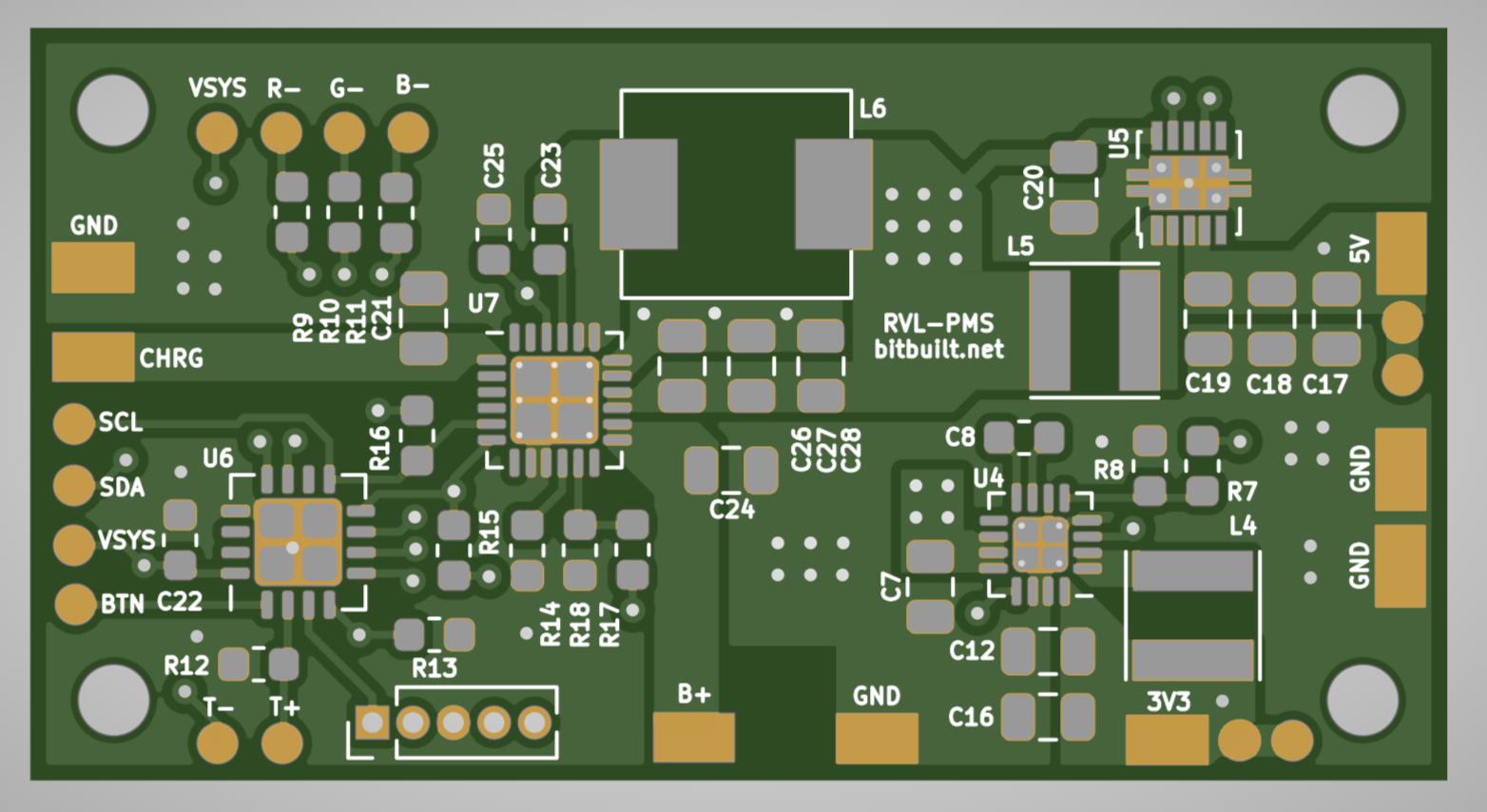
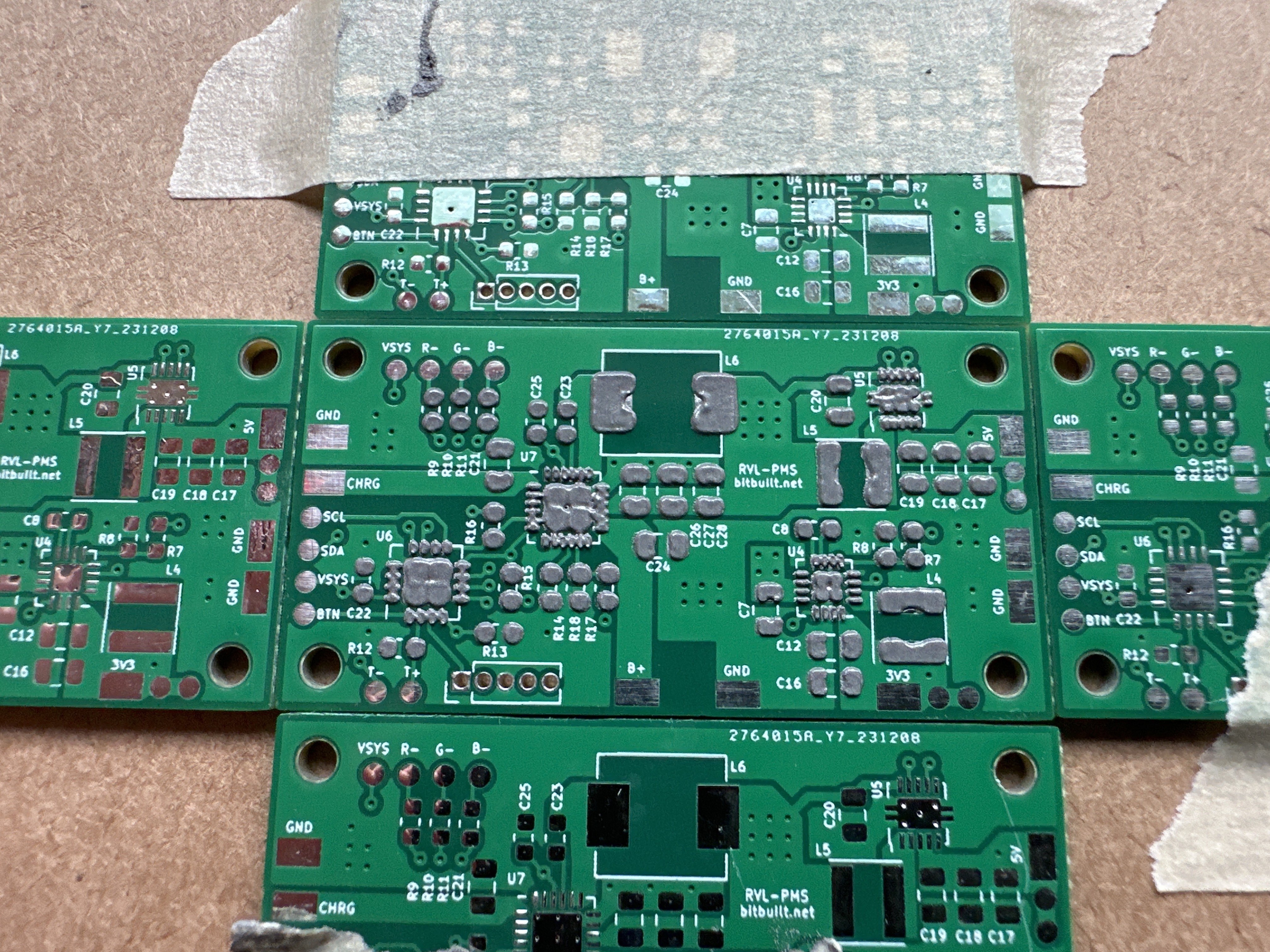
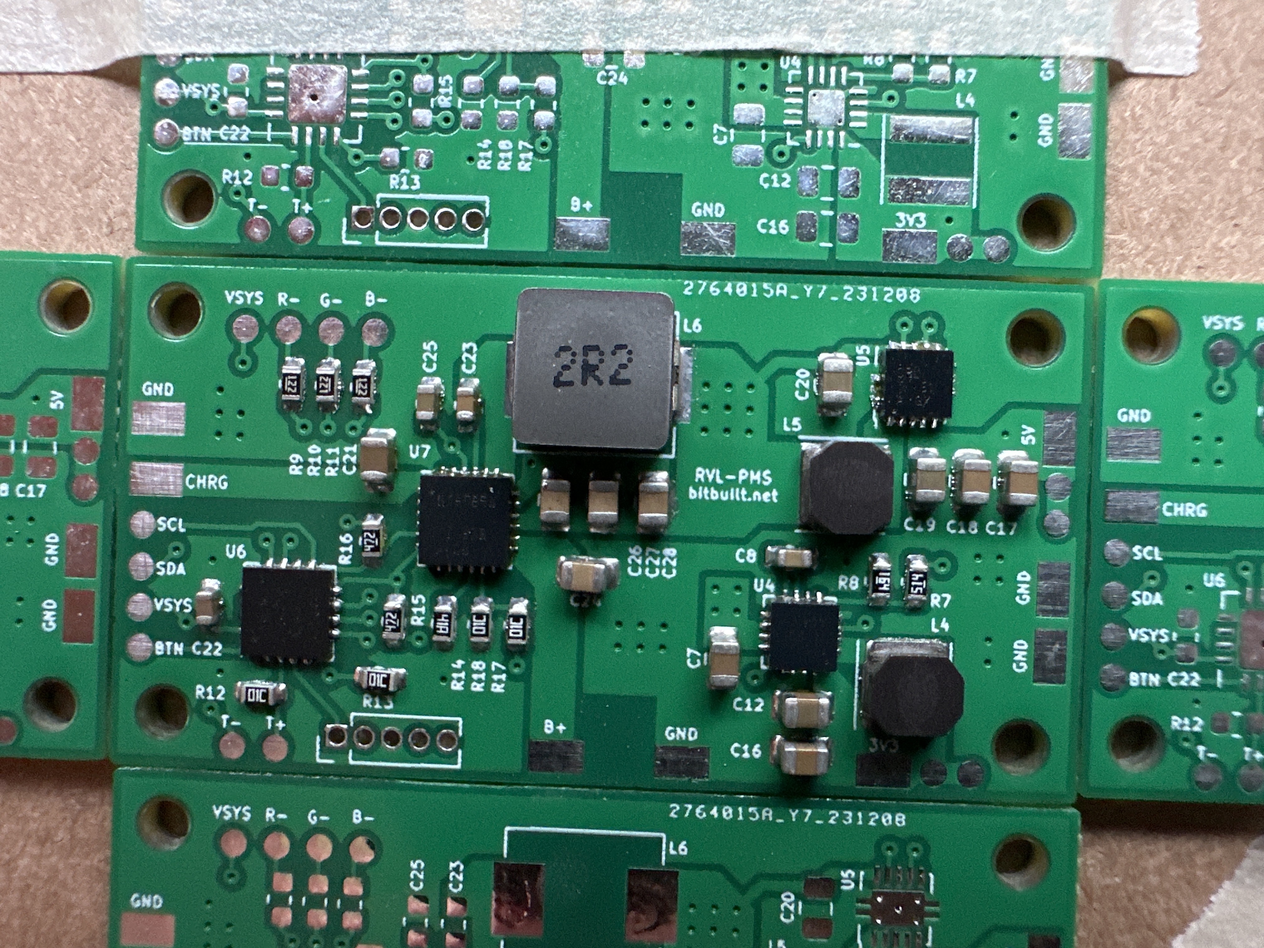
I wanted to redesign the RVL-PMS to get rid of the 1v, 1.15v, and 1.8v lines since they aren't needed for the N64. I have never done anything with KiCad before and it took me a little while to learn how to move things around properly. It was fun to modify a design, but I think it would be sweet to make my own pcb from scratch now. Once I had something I thought would work I sent off my order for the PCBs.
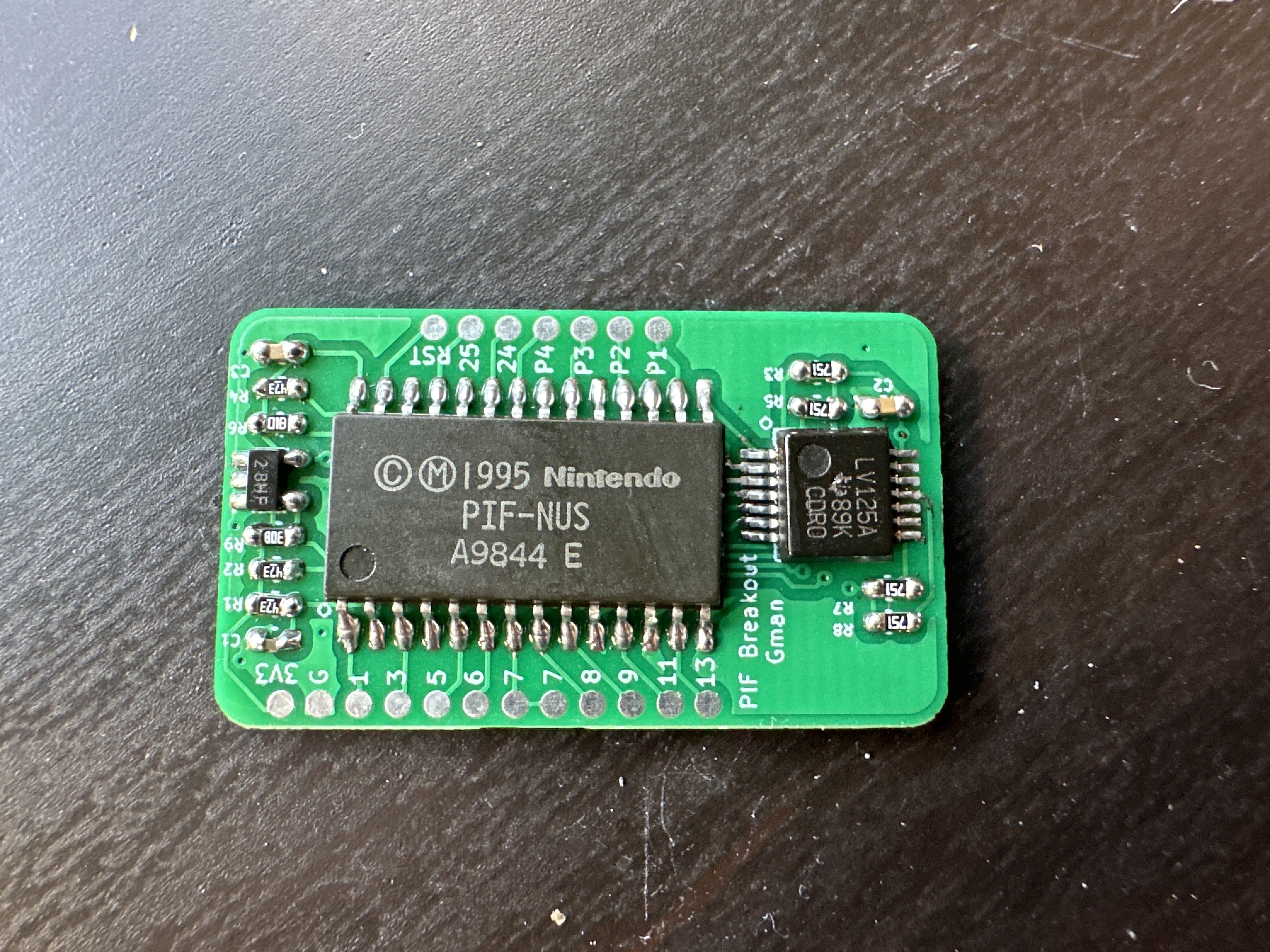
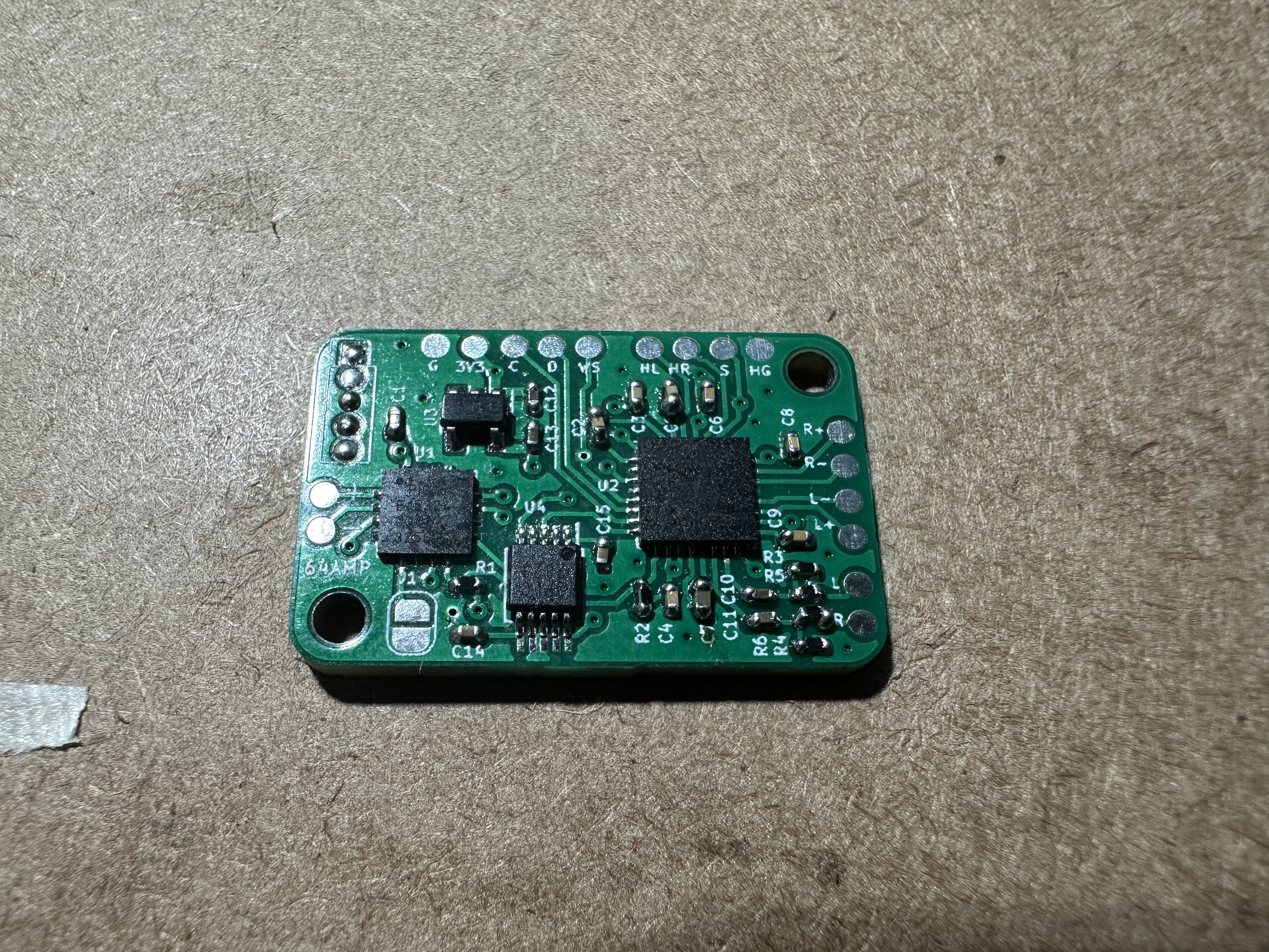
This was my first time ever buying blank boards and populating them by hand. The N64 Amp and PIF boards were done by hand and I did the PMS with a stencil. I wanted to try out some soldering methods that were new to me. After doing both methods I would say the stencil is the way to go. It was much faster and easier with less need for reworking after blasting the components with the hot air station.
Now that I had the boards populated, I had to learn how to program the PIC chips. It took a bit of research to learn what I needed to do exactly but I eventually found the MPLAB IPE program that would interface with my PICkit 3 clone. My first attempt with the N64 Amp didn't go well. I didn't understand the power settings needed to power the chip and kept getting short errors. I eventually took a break and moved onto the PMS instead. With sheer luck the PMS connected first try and I was able to successfully program my first chip! I went back to the N64 Amp and reworked things a bit more and finally got that one to program after changing the power settings to 3.3v.
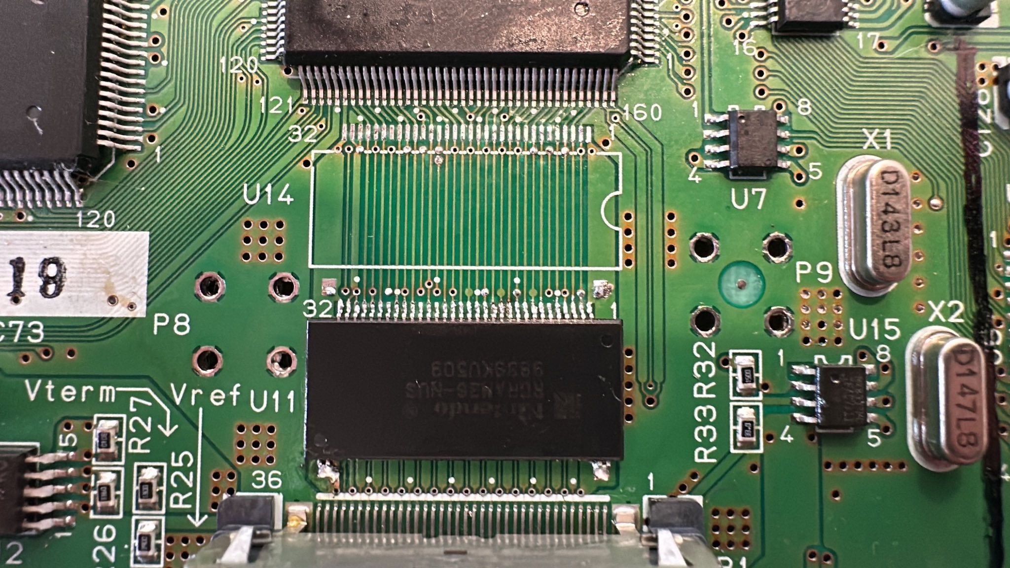
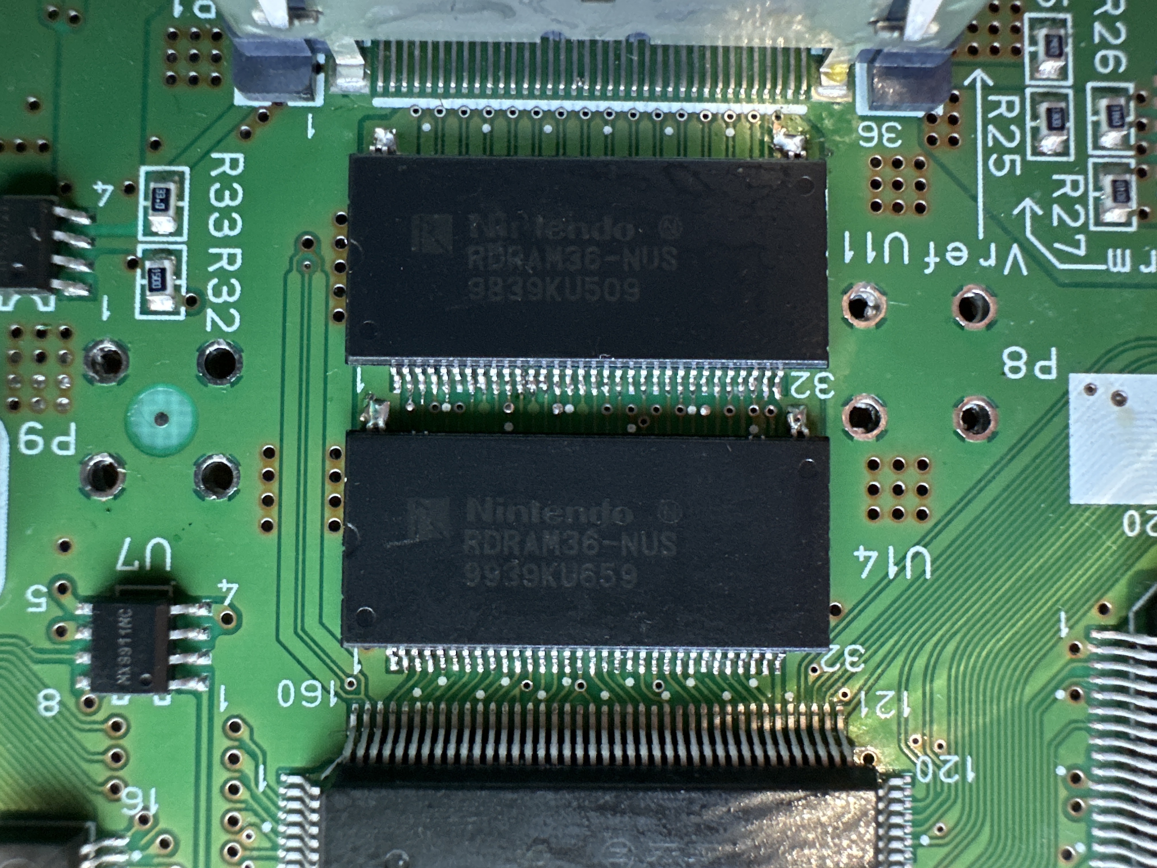
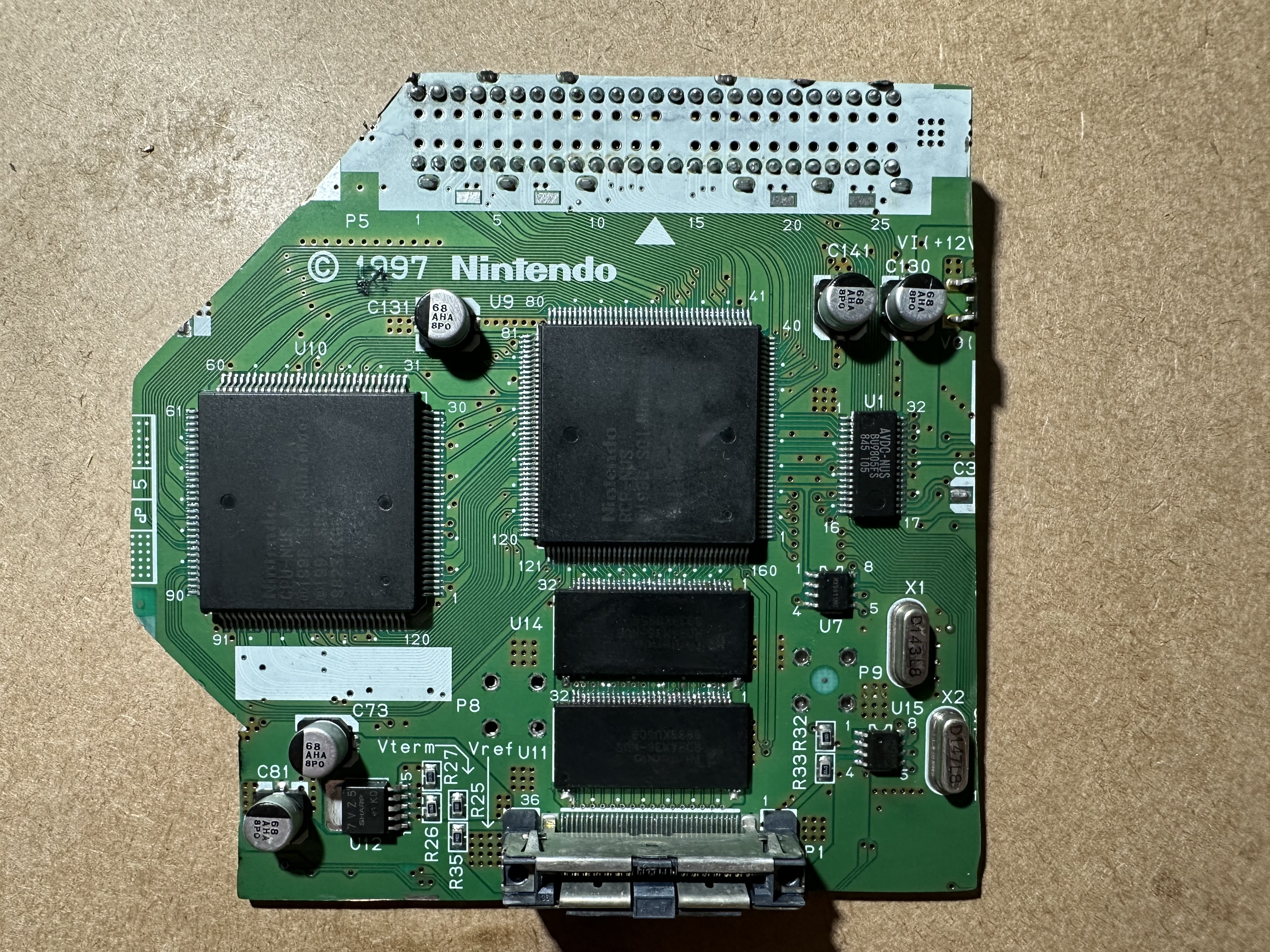
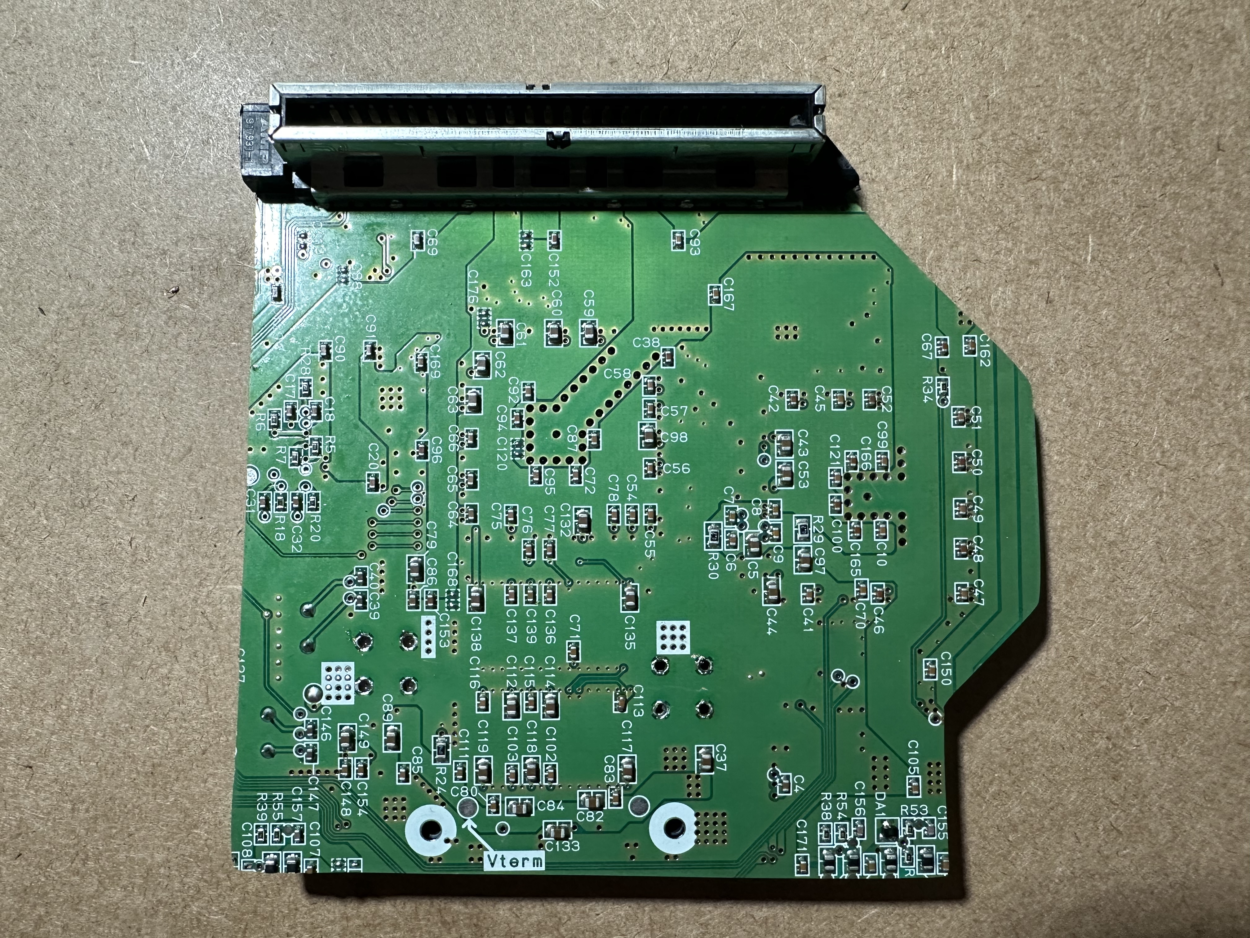
I then started to work on the N64 motherboard with first doing the RAM swap. I haven't done drag soldering before and it was a new technique I've been wanting to try. It started off a little rough with everything bridging like crazy. After a generous amount of flux and the help of some solder wick, I was able to get the chips soldered on.
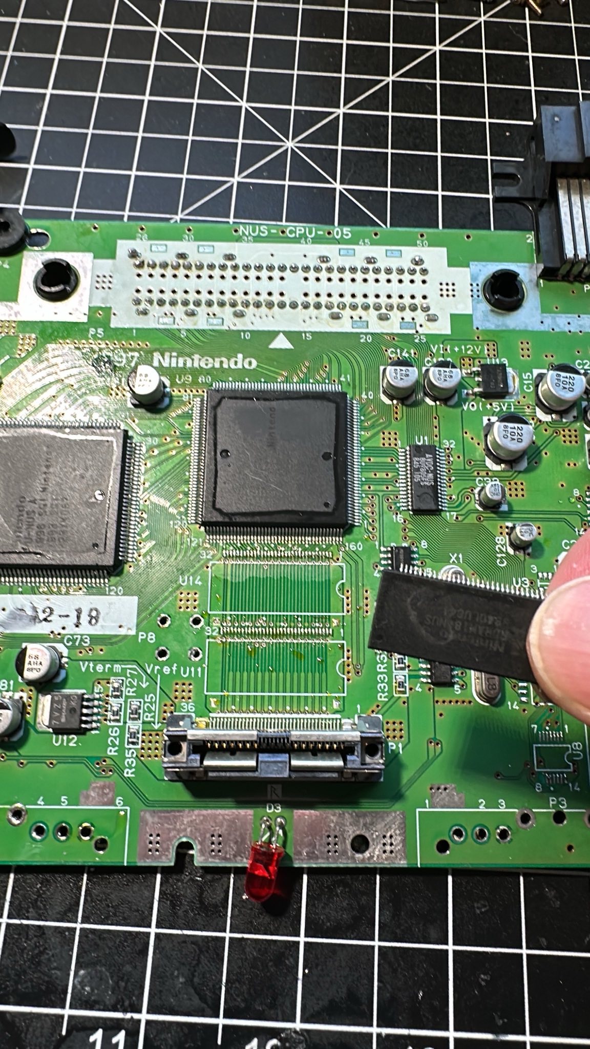
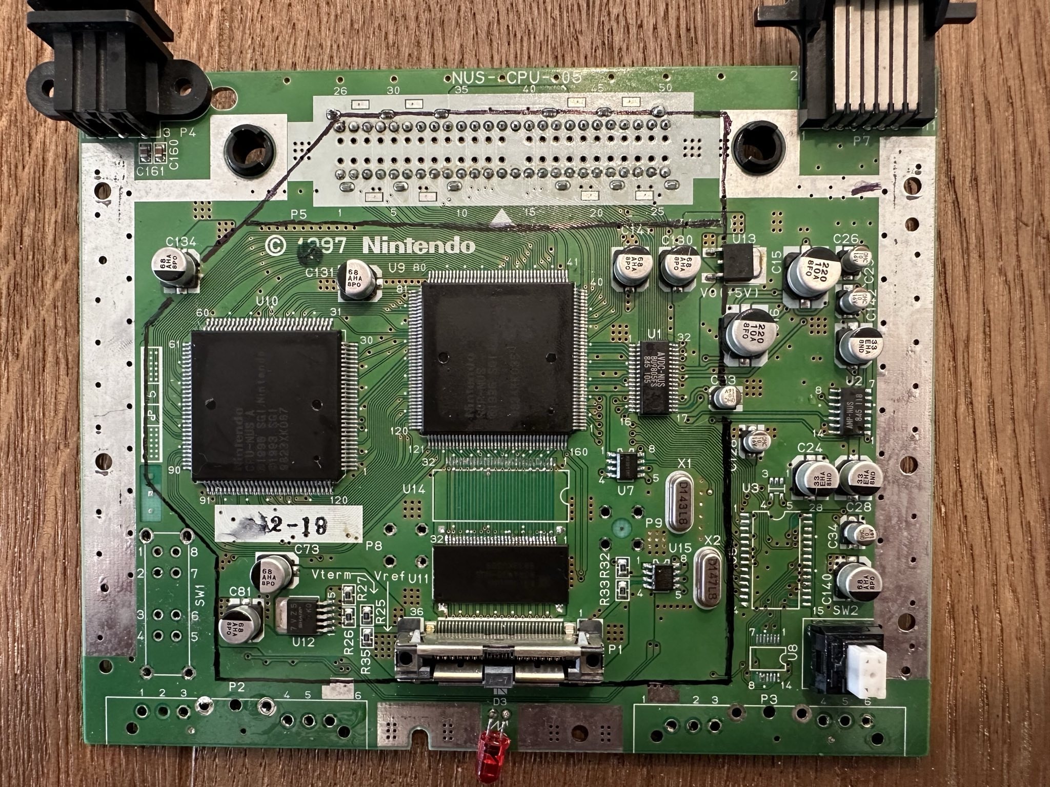
I believe I am ready to start trimming the motherboard down to finally test everything I've done so far.
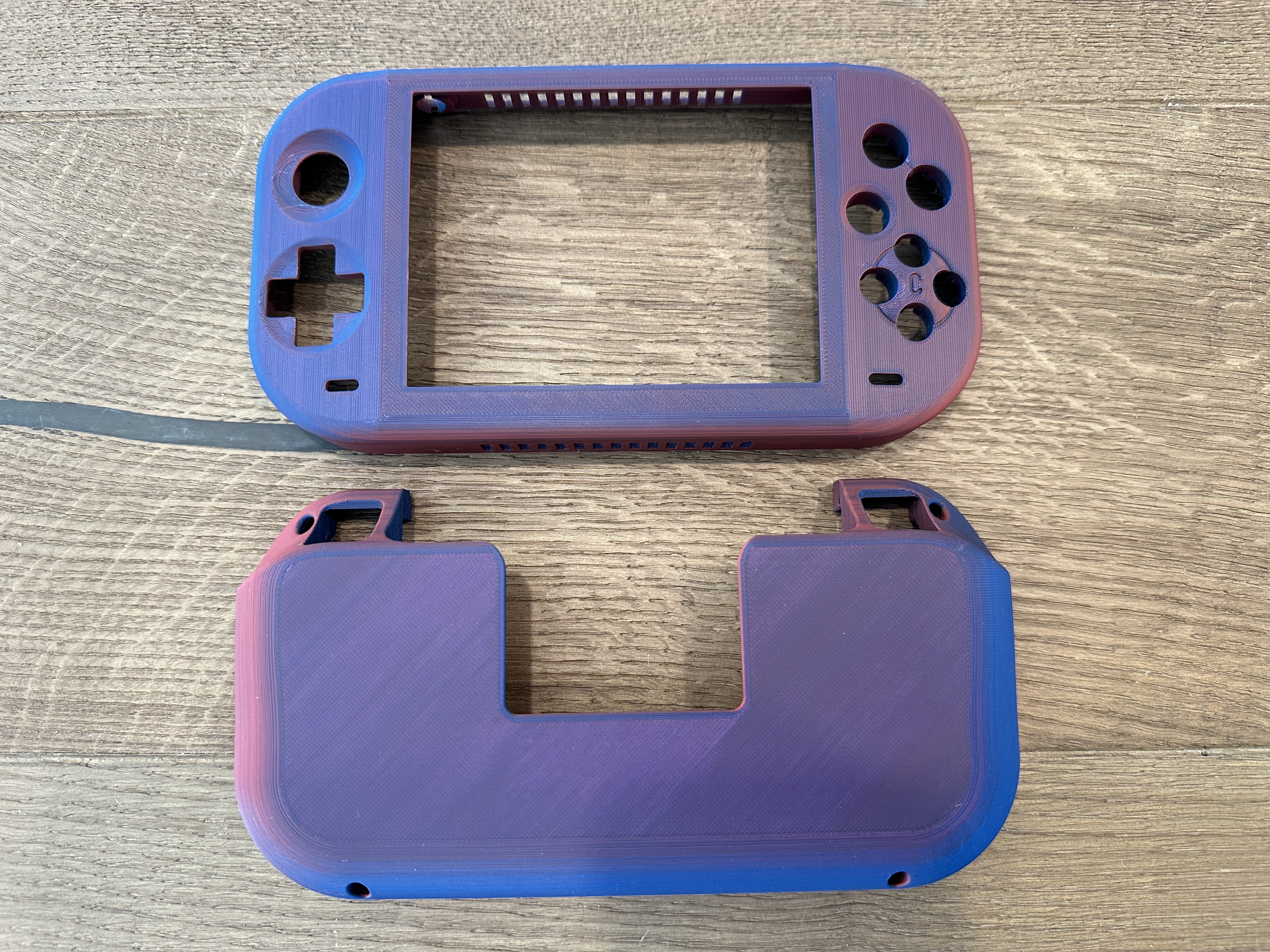
I next would decide on what I wanted to do for a case, and as luck would have it @Nicholas298 released his models right as I started this project. I have never done any 3d modeling myself and would like to learn one day, but for a first N64 build I figured it would be easier to use someone else's shared work. I will likely build another in the future to refine what I learn this first go around.
I am excited to see if all these new things I learned worked or not. I'm a bit nervous about the PMS working right, since that was the one thing I had to customize myself.
I'll keep updating here as I do things. I appreciate all the help from everyone so far!
Edit: I have now trimmed the motherboard as well. I still need to remove the cut through components. Hopefully I didn't cut anywhere I shouldn't have.
I first started with the main open source boards for the N64. I knew I would need the RVL-PMS, N64 Amp, and PIF relocations boards.
I wanted to redesign the RVL-PMS to get rid of the 1v, 1.15v, and 1.8v lines since they aren't needed for the N64. I have never done anything with KiCad before and it took me a little while to learn how to move things around properly. It was fun to modify a design, but I think it would be sweet to make my own pcb from scratch now. Once I had something I thought would work I sent off my order for the PCBs.
This was my first time ever buying blank boards and populating them by hand. The N64 Amp and PIF boards were done by hand and I did the PMS with a stencil. I wanted to try out some soldering methods that were new to me. After doing both methods I would say the stencil is the way to go. It was much faster and easier with less need for reworking after blasting the components with the hot air station.
Now that I had the boards populated, I had to learn how to program the PIC chips. It took a bit of research to learn what I needed to do exactly but I eventually found the MPLAB IPE program that would interface with my PICkit 3 clone. My first attempt with the N64 Amp didn't go well. I didn't understand the power settings needed to power the chip and kept getting short errors. I eventually took a break and moved onto the PMS instead. With sheer luck the PMS connected first try and I was able to successfully program my first chip! I went back to the N64 Amp and reworked things a bit more and finally got that one to program after changing the power settings to 3.3v.
I then started to work on the N64 motherboard with first doing the RAM swap. I haven't done drag soldering before and it was a new technique I've been wanting to try. It started off a little rough with everything bridging like crazy. After a generous amount of flux and the help of some solder wick, I was able to get the chips soldered on.
I believe I am ready to start trimming the motherboard down to finally test everything I've done so far.
I next would decide on what I wanted to do for a case, and as luck would have it @Nicholas298 released his models right as I started this project. I have never done any 3d modeling myself and would like to learn one day, but for a first N64 build I figured it would be easier to use someone else's shared work. I will likely build another in the future to refine what I learn this first go around.
I am excited to see if all these new things I learned worked or not. I'm a bit nervous about the PMS working right, since that was the one thing I had to customize myself.
I'll keep updating here as I do things. I appreciate all the help from everyone so far!
Edit: I have now trimmed the motherboard as well. I still need to remove the cut through components. Hopefully I didn't cut anywhere I shouldn't have.
Attachments
-
123.8 KB Views: 26
-
93.2 KB Views: 26
-
102.8 KB Views: 24
Last edited:
