Worklog Jack’s Ashida worklog

Joined
Oct 31, 2025
Messages
14
Likes
23
Location
United States of America
Hello everyone, I want to start off and give some backstory and context for myself and this worklog. I’ve wanted to get into portables for a while, I remember when the first few made their way onto the internet. As an adult with adult money I wanted to give it a try, my first attempt was in 2022; unfortunately I made the error of getting a 6-layer Wii and trimmed it slightly incorrectly as well as being new to soldering at the time (now in spare parts bin). Fast forward to the present I acquired another Wii and I wanted to try my hand at a more beginner friendly build with the Ashida.

Now bear with me a little because by trade I’m a mechanic (also worked as a diesel mechanic) so I am more familiar with larger electronics and harnesses. I got the Wii and verified it worked with this screen.

IMG_5731.webp


After verifying the Wii functioned properly, I homebrewed it and installed RVLoader, I patched out WiFi and left the video to composite (mostly because I figure it’ll be easier to wire)
IMG_5734.webp

After installing, I also the Wii down from its shell to just the motherboard and verified it still functioned properly.

IMG_5760.webp


Following this, I marked out the OMGWTF trim outline. I was planning on doing the U10 location before trimming however I decided to just wait until my RVL PMS board comes in.

IMG_5785.webp


IMG_5784.webp


Trimmed the board last night, as you can tell I have stayed outside my trim lines. I started sanding the edges, it’s not completely sanded yet however (LMK if there’s any obvious flaws here). I also went ahead and checked the resistance readings, I’ll post them in an update later as I still need to log them however, so far the readings check out within spec.

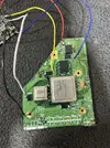
That’s all for today, has anyone seen this screen/ driver board before?
IMG_5761.webp


IMG_5762.webp


I cannot for the life of me find a break down or pin out of this driver board. If anyone know much about this one, can you let me know if I am able to use it in my build? (Just in case I’ve ordered the screen and board from 4layer tech as well)
 
Update

This will be just a small update. I cleaned up the Wii motherboard some more and sanded it more as well. I also rounded any sharp edges, I may go back and sand down the notch at the bottom of the board as well.

IMG_5833.webp


Following this I triple check all the resistance readings:

IMG_5834.webp


The readings look consistent with what should be expected for a successful trim. Some of the readings appear a little higher than expected but better that than too little resistance!

As of now I am just waiting for some of my boards to come in, I’ll have to order to GC +2 board and Ashida controller mounting boards as well but I want to wait until the RVL PMS and screen/driver board & shell to come in to verify everything works properly before focusing on the controller.
 
It's good that your trim resistances look good, but I will say that the edges of your trim still look rather jagged. The edges are supposed to look smooth like this:
1762202061439.webp


You don't need to round your corners or anything, but you really do need to sand until the edges are smooth. Most people start sanding with grits like 220 and then move up to 500, and finally finish sanding the board with 1000 grit. This leaves clean, smooth results that won't have any shorts so long as you sand at a slight angle.

Something else I'll point out is that you can, and probably should remove these aluminum capacitors by either de-soldering them, or simply ripping them out with a pair of pliers:
1762202434415.webp


Leaving them won't hurt anything, but they create clearance problems inside the shell of most portables, so removing them isn't a bad idea.
 
Progress update

So I took Cy’s advice and continued sanding my trim and removed as much of jagged edges as possible. Also my screen and PMS Lite came in

IMG_5878.webp


I’ve went ahead and wired up all the voltages lines to the PMS lite as well as wired up the battery holder, unfortunately my button won’t come until Monday I believe. So sadly I cannot report if my trim will power on yet, I also rechecked for shorts and resistances as well, everything is looking good so far. The voltage lines are color coded and ground is of course black.

I will wire the PMS and trim to the screen (or an AV cable if I’m lazy) and I will report back after wiring up the button as well hope it works out
 
so apparently after I posted this my Digikey order was dropped off :) so I got my button and tested it and…..

IMG_5879.webp


It works! I’m honestly a little surprised that I didn’t mess anything up since this is my first time trying this. I mean I do work with some electronics as a mechanic but that isn’t this micro soldering (half the time we crimp instead of solder anyway).
IMG_5880.webp


Please excuse my messy toolbox surface lol. Now I’m just waiting on my last set of boards to show up as well as my shell. I’ll update progress once those come and I get those started and any problems along the way.
 
Progress update

Good news my shell and buttons came in for my Ashida, as you can see I’m going for a black shell with translucent buttons, however I had messed up. So originally I had ordered a shell from AliExpress and this is what I got:
IMG_5901.webp

The shell is very nice, unfortunately this is not the correct shell. For anyone else that is also a beginner this shell uses a different design that is incompatible with the boards from 4layer tech, in hindsight I should’ve checked closer however the pictures on the shop looked very close to what it is supposed to look like. For reference:
IMG_5902.webp


Anyway luckily there’s a guy near me who was able to 3D print a correct shell for me. Here are some progress photos of it being printed.
683452a1a0a22e14ccc9b237088d0b55.webp
d06f5d30f108d928e2df12be71971683.webp

And here is the finished print:
IMG_5970.webp

IMG_5971.webp

I may sand the finished print, prime it, paint it, and then clear coat it. Although I do like the feel of the print so I’m a little undecided. The last batch of boards are coming in on Friday so I should be able to start assembling everything into the shell then :)
 
Progress update

Good news my shell and buttons came in for my Ashida, as you can see I’m going for a black shell with translucent buttons, however I had messed up. So originally I had ordered a shell from AliExpress and this is what I got: View attachment 40737
The shell is very nice, unfortunately this is not the correct shell. For anyone else that is also a beginner this shell uses a different design that is incompatible with the boards from 4layer tech, in hindsight I should’ve checked closer however the pictures on the shop looked very close to what it is supposed to look like. For reference:View attachment 40738

Anyway luckily there’s a guy near me who was able to 3D print a correct shell for me. Here are some progress photos of it being printed.View attachment 40739View attachment 40740
And here is the finished print:
View attachment 40741
View attachment 40742
I may sand the finished print, prime it, paint it, and then clear coat it. Although I do like the feel of the print so I’m a little undecided. The last batch of boards are coming in on Friday so I should be able to start assembling everything into the shell then :)
you can design a pcb
to accomdate pms and other item to use the good shell
 
you can design a pcb
to accomdate pms and other item to use the good shell
That is something I considered and will most likely do in the future however since I’m still relatively new to this I’m gonna stick with a previously documented design, also I bought all the materials from the BOM already.

Progress update:

So over the past couple days I sanded, primed, painted, and clear coated my she’ll and I have to say I’m quite satisfied and impressed with the results here are the progress of the painting:
IMG_5978.webp
IMG_5979.webp

And here are the final results:
IMG_5982.webp

I really like how the she’ll has turned out so far, it really feels like a premium controller and something you would buy. Following this I populated the controller boards with the GC+ (just need to finish the left trigger wiring)
IMG_5992.webp

IMG_5993.webp

I wanted to reuse the trigger mounts from the GameCube controller so I cut them down so they would fit ( I’ll go back and fix the edge on both sides before final assembly) I also started to wire everything up and assemble the shell:
IMG_5990.webp

So far the fan and batteries have been wired to the PMS board, the heat sinks have been put into place, and the interface board is just waiting on its final buttons.
 
Progress update

Made some more strides towards completion this week, after my previous progress I screwed down the interface board and the PMS lite. I also wired in the LED, although I don’t know how bright it’ll be through the layers of paint lol. I had the screen holder printed as well as the interface buttons. I also installed the RVL NTC as well:
IMG_6101.webp

Following this I wired up the Wii mobo as well as the RMS PD, I still have a few of the speaker wires to solder to the interface board. After all this I decided to quickly test it out and see if it boots into the SD card (had to get a new one with bigger storage)
Also I will take off the trigger mounts before final assembly keeping them on so I don’t lose them.
IMG_6102.webp

Here are the results of the test boot up, the screen is wired via AV still for testing purposes, I plan on installing the VGA patch and then wiring VGA as well.
IMG_6103.webp

IMG_6104.webp

And it works! Booted into RVLoader first time go. Next up will be wiring up VGA and the controller boards, still debating whether or not to install Bluetooth as well.
 

Attachments

  • IMG_5980.webp
    IMG_5980.webp
    1.2 MB · Views: 37
Well done! Home stretch now.

Although, I must say that the amount of exposed wire you have is giving me grave anxiety for long term reliability.
1763868433083.webp
1763868456414.webp
1763868409515.webp

If these move and touch anything conductive............... instant brick
 
Well done! Home stretch now.

Although, I must say that the amount of exposed wire you have is giving me grave anxiety for long term reliability.
View attachment 40800View attachment 40801View attachment 40799
If these move and touch anything conductive............... instant brick
Thanks for the advice, I cleaned up a lot of the problem areas to where I am satisfied that they won’t have a risk of touching anymore.

IMG_6175.webp

IMG_6174.webp

I will go through more of the wires and shorten up any other areas that may carry that risk.
IMG_6173.webp

I think I’ll also add either some electrical tape or Kapton tape to further mitigate this, I would prefer to use heat shrink but I don’t really want to melt the case or leave any burn marks. (Also don’t mind the messy solder on the ground pads, those are temporarily there while testing)
 
The hot air from a hair dryer is enough for heatshrink tubing. If you tape some cardboard around where you're blasting, it'll deflect enough heat to preserve the case
 
Progress update

Happy holidays! This will be a smaller update, progress has slowed due to the holidays plus it’s pretty cold to be working in the garage. After going through and fixing the areas of concern, I wired up all the audio interface board wires. Before I continued I had to wire the GC+ board and controller components up to re run the RVLoader installer. This is due to the fact that I had left the VGA patch off in the beginning of my build.

IMG_6219.webp

this is a picture of the installer re running with the VGA patch enabled (I had to do this at a awkward angle to see the screen) now I did have a weird issue when trying to do this and it has me a little stumped. Basically after I wired the controller and GC+ board I wasn’t getting any input from the controller, this issue was very odd because I triple checked all my wiring and everything was 1. Wired correctly 2. I had no shorts on anything 3. I was getting proper voltage to the GC+ board 4. The data line was sending signal when it was functioning properly. Now I think the solution to this issue was two things, first my batteries may have needed a recharge (I did recharge them and it worked following this), second my temporary wires were longer than I’d like and may be the culprit as well.

I think this issue will be resolved after re wiring the controller towards the end of the project. Anyway moving on from that I finished wiring up all the interface/ audio lines.
IMG_6676.webp
Next I’m going to clean up the remaining wires and start connecting the two halves together, I’m also going to be removing the trigger guards and finishing VGA. If I don’t update again before Christmas and new years then Happy Holidays to everyone!
 
Update

So I figured I’d finish this project I only had a few things left to do, for starters I finished wiring up VGA. I also finished wiring up the two halves of the shells together:

IMG_7601.webp

IMG_7602.webp

So now here’s where I am encountering problems to finish this project. First Wii is not taking any controller input. Which is really weird, this happened before but I figured it may be a wiring issue with the controller halves or even the batteries. However this was not the case, after finishing all the wiring I’ve been stuck and feels like I’m going insane right now. I rechecked my wiring for the GC data line and I’m getting continuity between the data line the P1 via as well as the D pad on the GC+. I’m getting 3.3V on the controller array, I’m also getting 3.3V on the GC+, both halves of the controller are receiving proper voltage and also have continuity where they should. My port shouldn’t be fried as it has worked with the GC+ initially and when doing the VGA patch. The P1 port also worked with a regular controller. The next thing I thought it could be was the U10, however that is also good, it receives a consistent 3.3V and it also consistently allows the system to boot. I also tried using the other P1 via, additionally I tried connecting the data line directly to the D pad on the GC+, I’m kind of at a loss for what to try next.

I know that the GC+ is tested from 4layertech before being shipped (worked prior as well), my wiring is correct with the data line and 3.3v, there aren’t any shorts, and the U10 is good as well ( I used the U10 emulation) and I’m positive the port isn’t fried. Oh and I check resistance, I’m getting a correct Ohm reading as well. Also I’m not quite sure why the screen is a bit off color yet…
 
Final Update

My project is essentially complete now. In case anyone comes upon my work log and hasn’t seen my other thread, the problem I was encountering with my GC+ controller was caused by the U10 having a very small amount of flux residue on it, it was very odd especially since the U10 wire was giving 3.3V despite having its connection somewhat interrupted by the flux residue. Anyway following this I was able to fix the color quality a bit and test out the peripherals:
IMG_7675.webp

Initially my speakers weren’t outputting any sound but I was getting sound from the headphone jack, the solution was to solder wires from the speakers to the pads on the ashida boards and this solved the issue straight away. Another initial issue was my triggers weren’t registering at all, this was fixed after finding the left trigger wasn’t completely connected and after reflowing they worked. However the triggers were constantly “pressed” while pressing them resulted in the neutral state, this was also an easy fix as it was just changing the triggers from digital to analog in RVloader’s settings. Following this I had to readjust the Z buttons because the shell wouldn’t close, this wasn’t that bad only a pain because of gravity (soldering while board was in odd position to not mess up everything else) and how tiny these buttons are.

IMG_7673.webp

IMG_7726.webp

The Ashida next to the Wii:
IMG_7727.webp

There are a few more kinks to work out but very minor stuff that I’ll do in the future.

Post Analysis:

Now this was a fun project to do, I feel like I’ve learned a lot about the Wii and portables. I believe the Ashida is a good first time project for anyone who would want to get into this, especially if you have any experience with electrical components and soldering. If you haven’t ever soldered before I’d strongly recommend practicing first to get at least a basic skill for it before jumping into a project like this, I went into this project with a small amount of soldering experience and now I am much more confident in my ability. After completing this project I have mixed feelings on this and other portables, on one hand I feel this is really cool to show off to friends and family, on the other hand I don’t see myself actually playing games on this long term. The Ashida has great from factor, everything functions almost seamlessly. I also appreciate the hard work that was put into this by Wesk and 4layertech team.

Some people online say “just get a steam deck” I am not going to say that. But as someone who owns a switch and a steam deck, I play games way more often on both systems than I see myself playing on this. Not in a bad way, let me explain…
IMG_7729.webp

In contrast to the steam deck, the Ashida runs real hardware and won’t have any problems related to emulation. Would I recommend buying the deck over doing this? No I still think portables and mods are valuable and I think it’s personal preference with this. It’s kind of like comparing a classic car restoration to a race car, both are very cool in their own ways and they don’t detract from each other but like the classic car (Ashida) I don’t want to drive it very often to keep it nice nor do I want to abuse it after all the hard work poured into it. The deck runs these games emulated, which while doesn’t beat out the actual hardware has its own set of benefits sometimes. Although I will say that if I didn’t own any devices like the deck or switch, I would definitely play the Ashida or another portable way more. However I cannot state enough how valuable building a portable is for developing an electronics skill set. In fact this project gave me the confidence to install a mod chip in my switch which highlights what you gain from doing a project like the ashida.
IMG_7550.webp

IMG_7552.webp

if you are on the fence about starting a portable I would say just go for it. I can see myself building another portable of my own design now. For the Ashida I may just give it to my son when he gets older, I know I would’ve killed for something like this as a child, for now I’m going to display it with my other consoles and tinker with it.
 
Back
Top