OMGWTF trim help!

Joined
Aug 26, 2025
Messages
9
Likes
7
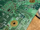
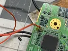
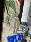
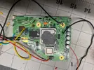
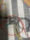
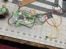
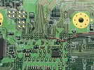
I am planning on making a portable ashida wii. I am up to the stage where I am testing the trim, and nothing is output to the tv. The trim and sanding went smoothly.

My suspects for the cause of why its not working are:

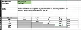
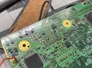
1. When I tried to remove the on board voltage regulator I accidentally took of some of the solder mask so I added a blue wire so the resistances lined up with the guide.
2. I had some trouble getting in the U10 via but I think I got it?
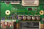
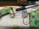
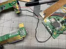
3. I wasnt able to remove the display port and for and after the attempt for removal the display port is a much looser connection.
4. In guides I see people wrap the ground and composite wires around each other, I assumed that didnt matter, but maybe it does.

Please let me know if you see anything else wrong, or if you have any advice! Thanks!

Edit:
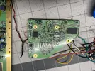
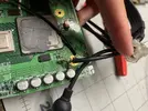
I've attached the images.
 

Attachments

  • IMG_3177.webp
    IMG_3177.webp
    728.4 KB · Views: 61
  • IMG_3176.webp
    IMG_3176.webp
    2.9 MB · Views: 58
  • IMG_3171.webp
    IMG_3171.webp
    3 MB · Views: 52
  • IMG_3174.webp
    IMG_3174.webp
    2.5 MB · Views: 59
  • IMG_3175.webp
    IMG_3175.webp
    1.6 MB · Views: 60
  • IMG_3165.webp
    IMG_3165.webp
    910.3 KB · Views: 55
  • IMG_3167.webp
    IMG_3167.webp
    890 KB · Views: 54
  • IMG_3168.webp
    IMG_3168.webp
    1.1 MB · Views: 61
  • IMG_3170.webp
    IMG_3170.webp
    2.9 MB · Views: 51
  • IMG_3173.webp
    IMG_3173.webp
    2.2 MB · Views: 59
Last edited:
We need to see pictures of your trim and soldering in order to help you. It's possible you trimmed something critical off the board and don't realize it, or maybe you went into an important component, or maybe your soldering isn't good. Regardless of what it is, we need pictures of the front and back of your trim in order to help you.
 
There's many different things that could be wrong. It's possible it could simply be that U10 wasn't relocated well, but it could also be something like your sanding, a component cut in half that bridges a connection that you'll need to remove, that blue wire isn't meant to be there maybe, or your TV just doesn't work properly with the video out for some reason. Regardless, I can't help you with anything unless you're able to post pictures of the Wii itself. Hopefully we can figure out the issue!

EDIT: Just saw his message come through now, but yeah, basically what Cy said lol.
 
Sorry I tried to upload pictures but I think the files size was too large for this website. I just made a google drive link with the images. Sorry!

Edit: Sorry again Ive uploaded the images to the original post after exporting.
 
Last edited:
Bash:
[crash@Zen Downloads]$ file IMG_3165.jpg
IMG_3165.jpg: TIFF image data, big-endian

Your images are raw TIFFs with a jpg file extension, and massive for being 12MP. Save them as jpegs and then upload them.
 
Thank you for your help and sorry for the technical difficulties. I have exported and uploaded the images to the original post. Please let me know what you think!
 
I know in a regular U10 relocation the three capacitors around the U5 footprint need to be removed, I've noticed that they're still present here, so I'm not sure if that's an issue or not. Your wires are long and not super well organized which is making this harder to follow. Also, you've exposed way more of the wire than you need to, especially on the B- wire for the PMS2, this creates some really nasty shorting potential if the wire touches anything of the other connections.

I'm unable to see the full back of your trim which has key trim points that we check for that aren't really visible here. I've noticed you're connecting your video signal to the trimmed off part of the Wii for testing purposes, this could be a problem on it's own given that the layers needed to be sanded to prevent shorts. Your composite video signal very well may just be shorting to ground (or other parts of the trimmed off board that could be causing issues) since the area around your connector hasn't been sanded. I would also check to make sure that none of your voltages are shorted to ground (note that 1.8v always has low resistance to ground).

There's probably more that I could say about this, but I'll leave it at this for now.
 
Thank you so much for your help! The composite video WAS being shorted to ground, so I desoldered both the video wire and ground wire. I am unable to remove the display connector, so how should I test the wii? Could I wire it directly to a composite video cable? or should I test with the Ashida screen?

I have attached my voltages and an image of the back of the wii.

Please let me know if you have any more guidance!
 

Attachments

  • Screenshot 2025-08-27 at 2.53.55 PM.webp
    Screenshot 2025-08-27 at 2.53.55 PM.webp
    78.9 KB · Views: 76
  • IMG_3184.webp
    IMG_3184.webp
    1 MB · Views: 55
  • Like
Reactions: cy
Yes, you could solder directly to a shielded composite video cable. I've seen some people cut apart the Wii's OEM one to use, but I would say just use a junk one that you have.
Soldering the connector just makes it an easier setup for some people, as they probably already have Wii cables that can plug into their television, or an HDMI adapter, etc. as they had to have jailbroken the Wii already.
 
  • Like
Reactions: cy
Thank you so much for your help! The composite video WAS being shorted to ground, so I desoldered both the video wire and ground wire. I am unable to remove the display connector, so how should I test the wii? Could I wire it directly to a composite video cable? or should I test with the Ashida screen?

I have attached my voltages and an image of the back of the wii.

Please let me know if you have any more guidance!
It's pretty standard to just solder composite video to the screen driver board. Be aware that in order for you to get video output, you must have the screen set to the correct video mode. This means toggling through each video mode until you get video output from the Wii onto the screen for the first time, after that you can leave it. The back of your Wii looks good and I'm not seeing any of the "usual suspects" for something that would kill a motherboard. You've done a good job of trimming within the line, and there isn't anything clearly wrong. Your resistances also seem to be in the general ballpark looking at them and comparing them with Nold's example.

I think your trim is functional, you just need to do a bit of a better job having shorter tinned wire ends. Obviously you need to find a way to test with composite video that doesn't short the video signal to ground too haha. I'm glad you found one of the problems though. Hopefully it just works after this!
 
Personally I would clean all that burnt flux off of the board with some isopropyle alcohol as well. That stuff tends to cause random failures that make other issues harder to diagnose.
 
Hi thank you all! I tested again with a direct composite video cable but still nothing, though I do feel the trim getting warm (hopefully thats a good sign). I'm going to try and clear the melted flux with ipa, and shorten the wires next, and maybe try soldering directly on to the driver board.

My battery has about 3.4v and I just want to make sure thats enough. Also I found that the outer part of most the capacitors are being shorted to ground (the ones highlighted in the images). Is this a side effect of the trim? or is this just how it reads when there no power being supplied?

I just want to make sure that these aren't problems I should be concerned about.
Thanks you again!!
 

Attachments

  • IMG_3191.webp
    IMG_3191.webp
    501.4 KB · Views: 59
  • Screenshot 2025-08-28 at 11.02.06 AM.webp
    Screenshot 2025-08-28 at 11.02.06 AM.webp
    631.4 KB · Views: 88
Yeah definitely try that all before declaring the trim to be bad.

Should be enough! I believe that's what I ran my trim off of to test it. Those capacitors are for filtering video, and are meant to be connected to ground, so that's all good!

Hopefully you're able to get the video displaying soon!
 
Hi thank you all! I tested again with a direct composite video cable but still nothing, though I do feel the trim getting warm (hopefully thats a good sign). I'm going to try and clear the melted flux with ipa, and shorten the wires next, and maybe try soldering directly on to the driver board.

My battery has about 3.4v and I just want to make sure thats enough. Also I found that the outer part of most the capacitors are being shorted to ground (the ones highlighted in the images). Is this a side effect of the trim? or is this just how it reads when there no power being supplied?

I just want to make sure that these aren't problems I should be concerned about.
Thanks you again!!
You wired to the wrong side of that cap, we usually remove those large caps by twisting them off with pliers since they aren't needed anyways. It's possible that since you didn't remove the cap that it should still be outputting video, but I would 100% try wiring to the other side of that cap - I know the AVE sends it's video signal down from a via on that other side you haven't wired to.
 
You wired to the wrong side of that cap, we usually remove those large caps by twisting them off with pliers since they aren't needed anyways. It's possible that since you didn't remove the cap that it should still be outputting video, but I would 100% try wiring to the other side of that cap - I know the AVE sends it's video signal down from a via on that other side you haven't wired to.
Ok thank you! I've actually tried connecting it to the other side first but it had continuity with ground, so I changed it to the other side. Ill it try again. Thanks
 
I tried it and its still being shorted to ground even when power is connected. I'm a bit confused is it supposed to be connected to ground or not?
 
Yes, the one side of the capacitor is meant to be connected to ground. Like I said above, it's meant to filter the video signal.
 
I know in a regular U10 relocation the three capacitors around the U5 footprint need to be removed, I've noticed that they're still present here, so I'm not sure if that's an issue or not. Your wires are long and not super well organized which is making this harder to follow. Also, you've exposed way more of the wire than you need to, especially on the B- wire for the PMS2, this creates some really nasty shorting potential if the wire touches anything of the other connections.
Also by the way I did not relocate U10 because according to this video I was following: I thought it wasn't necessary because the function is built into pms2?
 
Back
Top