
You are using an out of date browser. It may not display this or other websites correctly.
You should upgrade or use an alternative browser.
You should upgrade or use an alternative browser.
Question Do I need to purchase a new pcb set?
- Thread starter Sully_:0)
- Start date
- Joined
- Nov 25, 2022
- Messages
- 89
- Likes
- 15
- Portables
- 1
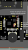
helloooo again , Quick question on the diagram it says to “solder this jumper closed” although I am not sure what it is talking about.
I attached a photo of my audio board and the diagram, thanks!
**edit**
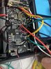
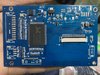
Another question I just ran into - do I need to connect the 3.3v pad on the pms-pd (usb-c board) to the PMS? On the pms diagram it didn’t say to but on the usb-c board diagram it did. - Attached a photo of my usb-c board
I attached a photo of my audio board and the diagram, thanks!
**edit**
Another question I just ran into - do I need to connect the 3.3v pad on the pms-pd (usb-c board) to the PMS? On the pms diagram it didn’t say to but on the usb-c board diagram it did. - Attached a photo of my usb-c board
Attachments
Last edited:
The U-Amp has jumper pads so users can set it to the correct mode for different consoles. The simplified RVL-Amp that you have only works on the Wii, so it has no jumper pads.helloooo again , Quick question on the diagram it says to “solder this jumper closed” although I am not sure what it is talking about.
I attached a photo of my audio board and the diagram, thanks!
**edit**
Another question I just ran into - do I need to connect the 3.3v pad on the pms-pd (usb-c board) to the PMS? On the pms diagram it didn’t say to but on the usb-c board diagram it did. - Attached a photo of my usb-c board
And yeah the PD does need to be fed 3.3v in order to work.
- Joined
- Nov 25, 2022
- Messages
- 89
- Likes
- 15
- Portables
- 1
Okay sick thanks, also what type of flash drive or memory card goes into the PD?
**edit** Also, there are only 3, 3.3v pads on the PMS. It says one goes to the wii, audio board, PD board, and also the controller pcb board. Do I just try to fit a 4th 3.3v wire onto the PMS even though there are only 3 pads? Or is there another solution? Could I wire 3.3v from the wii to the controller pcb board? Thanks again
**edit** Also, there are only 3, 3.3v pads on the PMS. It says one goes to the wii, audio board, PD board, and also the controller pcb board. Do I just try to fit a 4th 3.3v wire onto the PMS even though there are only 3 pads? Or is there another solution? Could I wire 3.3v from the wii to the controller pcb board? Thanks again
Attachments

Last edited:
The PD was originally designed for the Kingston FCR-MRG2 MicroSD to USB adapter, but that seems to have gone out of production. Nowdays the I believe the Samsung Fit Plus 3.1 is the recommended drive. Most USB drives and USB 2.0 MicroSD adapters should work aside from some known offenders reported in the RVLoader thread, so there's room to experiment.Okay sick thanks, also what type of flash drive or memory card goes into the PD?
**edit** Also, there are only 3, 3.3v pads on the PMS. It says one goes to the wii, audio board, PD board, and also the controller pcb board. Do I just try to fit a 4th 3.3v wire onto the PMS even though there are only 3 pads? Or is there another solution? Could I wire 3.3v from the wii to the controller pcb board? Thanks again
Yeah you can run a wire from a 3.3v location on the Wii to the Controller PCB. All the 3.3v pads are linked, so you can use any 3.3v location of any connected board like an powerboard extension socket. You don't have to have everything connected directly to the PMS. Being connected to a board that's connected to the PMS works just as well
- Joined
- Nov 25, 2022
- Messages
- 89
- Likes
- 15
- Portables
- 1
Its weird to me that it works like that but thanks that helps a ton. -- so when we were talking about setting up menu controls. Where is up and menu on the driver board?
Attachments
That I'm afraid I don't know, that's the new driver board and I've never used it. You'll have to test them to find out, or perhaps ask Gunnar?
EDIT: To clarify, K1-K5 are the button pads but I don't know which pad corresponds to which button.
EDIT: To clarify, K1-K5 are the button pads but I don't know which pad corresponds to which button.
- Joined
- Nov 25, 2022
- Messages
- 89
- Likes
- 15
- Portables
- 1
That I'm afraid I don't know, that's the new driver board and I've never used it. You'll have to test them to find out, or perhaps ask Gunnar?
EDIT: To clarify, K1-K5 are the button pads but I don't know which pad corresponds to which button.
okay no worries man, if I just started testing the random k1-k5 would that do any damage if I solder it to the wrong one? --- also there is a ground, IR, and VCC pad along side the k1-k5 pads, do you know if I need to solder wire to those also?
I can try to get a hold of Gunnar, I also don't have a problem with the trial and error method.
** edit **
Also while I have you here, and sorry for the overload of questions this week, after looking at the wii trimming guide I am not entirely sure where the B-in, R-in, G-in, and AV-CVBS lines go. ------annnndddddd do I need AV-CVBS1 and AV-CVBS2?
Last edited:
If you solder a wire to a ground location and poke the papds with the other end of the wire, it will simulate pressing a button. If that board only requires grounding the pins to register inputs, then it should allow you to identify which pad is tied to which button. The VCC and IR pads are for if you're using an infrared remote control, which we aren't so you can ignore them.okay no worries man, if I just started testing the random k1-k5 would that do any damage if I solder it to the wrong one? --- also there is a ground, IR, and VCC pad along side the k1-k5 pads, do you know if I need to solder wire to those also?
I can try to get a hold of Gunnar, I also don't have a problem with the trial and error method.
** edit **
Also while I have you here, and sorry for the overload of questions this week, after looking at the wii trimming guide I am not entirely sure where the B-in, R-in, G-in, and AV-CVBS lines go. ------annnndddddd do I need AV-CVBS1 and AV-CVBS2?
The RGB in pads should be wired to the corresponding RGB out locations shown in the Audio/Video Out section of the Trimming Guide. Just make youre you wire them according to the legend designation, rather than the colour of the pads in the images. The colours are for the old Component video lines, and VGA out uses RGB instead. So while pin 7 on the AV port is green coloured, it's actually the R line for VGA. It's confusing, but those images were made long before the VGA patch was a thing and haven't been updated yet. AV-CVBS1 should be connected to the Wii's composite line, and the Wii's mode pin should be connected to 3.3v once composite video out is confirmed to work.
- Joined
- Nov 25, 2022
- Messages
- 89
- Likes
- 15
- Portables
- 1
so I can solder the RGB and composite lines to these things? Just asking since it looks the easiest
*edit* also the ground wires for each RGB connection - I can connect them to any ground point on the wii right? I do have each corresponding ground to RGB lines twisted together.
*edit* also the ground wires for each RGB connection - I can connect them to any ground point on the wii right? I do have each corresponding ground to RGB lines twisted together.
Attachments
Last edited:
Yeah you can solder the wires there if you find it easier, makes no real functional difference. Also yes any ground location on the Wii will doso I can solder the RGB and composite lines to these things? Just asking since it looks the easiest
*edit* also the ground wires for each RGB connection - I can connect them to any ground point on the wii right? I do have each corresponding ground to RGB lines twisted together.
- Joined
- Nov 25, 2022
- Messages
- 89
- Likes
- 15
- Portables
- 1
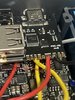
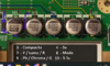
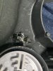
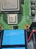
Okay so I am soldering the L shaped board to the WII. I wanted to test continuity and saw I was not getting a reading through this piece{blue circle} I see the number labeled on this piece is 330 while the others are 150 or lower. Is it possible my multi meter is just not able to register continuity on this particular piece? I did solder to it already but I don’t think I damaged it , but It’s possible I suppose
**edit**
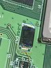
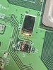
After further testing I noticed I am getting continuity from this red circled point to the other red circle. I don’t really know what the piece is or how they connect but I figured that would help troubleshoot.
*****edit **** edit ******
Okay okay so I think everything is fine. I think it has something to do with resistance or something. After checking the blue circles again the reading on my multi meter actually shows something just doesn't beep.. It reads somewhere around 150-170 and the others read somewhere around 35-40. Feel free to inform me if you would like but I am pretty sure all is good!!
**edit**
After further testing I noticed I am getting continuity from this red circled point to the other red circle. I don’t really know what the piece is or how they connect but I figured that would help troubleshoot.
*****edit **** edit ******
Okay okay so I think everything is fine. I think it has something to do with resistance or something. After checking the blue circles again the reading on my multi meter actually shows something just doesn't beep.. It reads somewhere around 150-170 and the others read somewhere around 35-40. Feel free to inform me if you would like but I am pretty sure all is good!!
Attachments
Last edited:
- Joined
- Nov 25, 2022
- Messages
- 89
- Likes
- 15
- Portables
- 1
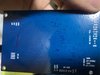
But I did end up breaking this screw post pretty bad. (Screw post unusable now). I was going to just use gorilla glue and hopefully get the board secured down that way. Any advice for this?
It’s the only screw post for the left controller pcb board
It’s the only screw post for the left controller pcb board
Attachments
Last edited:
If you don't get a readout when measuring resistance, raise the max value on the multimeter. Also trying to measure resistance from both ends of a capacitor can be fucky.Okay so I am soldering the L shaped board to the WII. I wanted to test continuity and saw I was not getting a reading through this piece{blue circle} I see the number labeled on this piece is 330 while the others are 150 or lower. Is it possible my multi meter is just not able to register continuity on this particular piece? I did solder to it already but I don’t think I damaged it , but It’s possible I suppose
**edit**
After further testing I noticed I am getting continuity from this red circled point to the other red circle. I don’t really know what the piece is or how they connect but I figured that would help troubleshoot.
*****edit **** edit ******
Okay okay so I think everything is fine. I think it has something to do with resistance or something. After checking the blue circles again the reading on my multi meter actually shows something just doesn't beep.. It reads somewhere around 150-170 and the others read somewhere around 35-40. Feel free to inform me if you would like but I am pretty sure all is good!!
Those two red points should have continuity, as they're both ground locations.
Well normally that would indicate a short, but the 1.15v line only has a 40-50 odd ohm resistance to GND. Some multimeters with improper tuning in continuity mode will beep at that resistance. Set the resistance range to the lowest setting and check the value on screen, if it isn't like 20ohm or less, you're goodAccording to the voltage guide - this red circle should be 1.15v. Why am I getting continuity from that and ground?
- Joined
- Nov 25, 2022
- Messages
- 89
- Likes
- 15
- Portables
- 1
Thank you for the quick response! I am so dang close. SO a couple questions real quick...
1. do I need the U10 pad on the PMS?
2. Do I need the T+ pad on the PMS? If so I would just wire it to 1.8v on the wii?
3. I saw that on the PMS diagram it says SC and SD are not used on Rev b. Just wanted to be sure - I don't need those either right?
**edit** Man I am sorry for all the questions but I figured I would add a couple more so I don't need to post later...
4. You mentioned 3.3v will go to mode. Can I use magnet wire for this? That mode via looks like it would be hard with the stranded wire
5. It looks like I also don't need 5v, is that right?
Thanks again!!!
Last edited:
Thank you for the quick response! I am so dang close. SO a couple questions real quick...
1. do I need the U10 pad on the PMS?
2. Do I need the T+ pad on the PMS? If so I would just wire it to 1.8v on the wii?
3. I saw that on the PMS diagram it says SC and SD are not used on Rev b. Just wanted to be sure - I don't need those either right?
4. You mentioned 3.3v will go to mode. Can I use magnet wire for this? That mode via looks like it would be hard with the stranded wire
Thanks again!!!
- The U10 pad on the PMS is a quality of life feature to replace the U10 relocation entirely. Since you have already done the U10 relocation, you can ignore the U10 pad on the PMS. There's no functional benefit to using one over the other, aside from the PMS U10 pad being simpler to use.
- You can ignore the T+ pad. The T+ pad on the PMS is for connecting to a generic thermistor. The RVL-NTC that comes with the PMS taps a 1.8v supply directly from the Wii, so only the T- signal pad needs to be used for it.
- SC and SD are not used in the PMS-PD Revision B, as the new PMS line of boards are smart enough to not need them. The pads remain on the PMS-2 and PMS-Lite for backwards compatibility with the RVL-PD Revision A, but since you have a PD Revision B you can just ignore them. SCW and SDW however, are separate data lines for connecting the PMS to the Wii (hence the W in the pad designation) to enable on-screen display of charge and battery status + RVL-AMP integration.
- Yeah you can use magnet wire for MODE, it's just a signal pin and doesn't need much current.
Yup!
Similar threads
- Replies
- 2
- Views
- 2K