I guess that the title says it all... is the 64CC Portable edition only for use with an original N64 controller or will it work with a really generic 4 wire aftermarket. You can see from the picture what I'm dealing with... and OEM controllers are hard to come, (more rare) and way more expensive. Just figured I would ask before buying one. ")
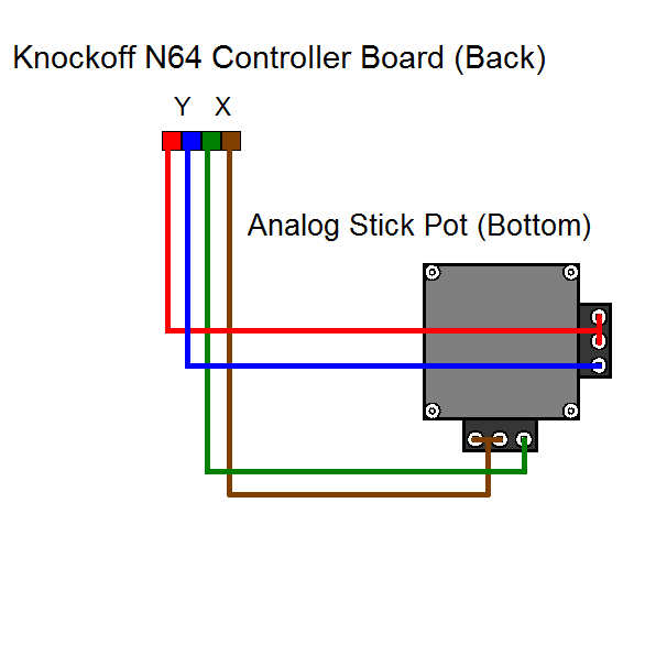
The wiring for every generic N64 controller I've found thus far...

The wiring for every generic N64 controller I've found thus far...
Last edited:
 .
.
")