
Hi all,
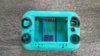
Because I had a spare Gamecube Component Cable video chip and Motherboards laying around, I decided to make a VGA compatible Portable like my second blue one.
Most likely after this one I will venture into Wii Portables, givin I get my hands on some cheap 4 layer NTSC boards and GC video gets a Wii release or someone commissions me ofcource.
Features:
- Zenloc Custom regulators
(1.62v CPU, 1.812v GPU "apparently needed for VGA/Component to work properly", 3.3v main and 5v rumble internal, external and maybe screen)
- Gamecube NTSC-U IPL 1.0
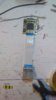
- Gamecube Componenten Cable VGA mod
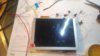
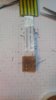
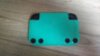
- 5" LCD screen Innolux AT050TN22 with KYV-N2-V1 driverboard (These screens support both 480i and p signals. So no black screen on Bios menu! The driverboard is big but still fits behind the screen. Works on 5v as well without issues)
- Wasp Fusion with Swiss and Micro SD slot mod
- Internal 256mb memorycard on Slot A
- SD-GECKO on Slot B with memorycard adapter for file transfer.
- 4 x Panasonic NCR18650B cells (6800mAh 7.2v)
- 4 player external support with switch for Player 1
- Internal speakers and AMP
- Rumble
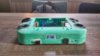
- Original Gamecube buttons and layout
- AV out (considering VGA or Component and composite for non HD tv's)
- Trimmed heatsink with small Asus fan
These features may change during the cource of this build.
I will update the first post with pictures and Progress.
Hope you enjoy and wish me no issues hahaha
Edit:
02-08-2017
Pictures added.
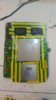
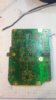
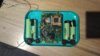
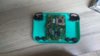
-Trimmed motherboard hybrid cut
-5" LCD screen
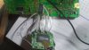
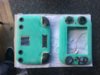
-Homemade Wasp Fusion adapter for testing
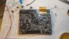
-Gamecube Component cable chip wired for testing
02-08-2017 part 2
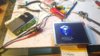
-Picture with component cable attached and displaying bios menu.
-Changed Component wires from chip to motherboard. Ide to multistranded wire for better signal.
(Found out I have a dead pixel arggg, but we must go on! "Fixed")
02-10-2017
-Wasp Fusion, internal 250mb memorycard and SD-Gecko wired (SD-Gecko only wires)
-Bottom half case cut to my desired height and rough placement
02-14-2017
-shoulderbutton holders and multiplayer ports added
06-09-2017
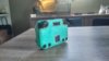
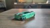
-case almost done, little bit of standing required.
09-12-2017
Some case work done.
Enjoy
Because I had a spare Gamecube Component Cable video chip and Motherboards laying around, I decided to make a VGA compatible Portable like my second blue one.
Most likely after this one I will venture into Wii Portables, givin I get my hands on some cheap 4 layer NTSC boards and GC video gets a Wii release or someone commissions me ofcource.
Features:
- Zenloc Custom regulators
(1.62v CPU, 1.812v GPU "apparently needed for VGA/Component to work properly", 3.3v main and 5v rumble internal, external and maybe screen)
- Gamecube NTSC-U IPL 1.0
- Gamecube Componenten Cable VGA mod
- 5" LCD screen Innolux AT050TN22 with KYV-N2-V1 driverboard (These screens support both 480i and p signals. So no black screen on Bios menu! The driverboard is big but still fits behind the screen. Works on 5v as well without issues)
- Wasp Fusion with Swiss and Micro SD slot mod
- Internal 256mb memorycard on Slot A
- SD-GECKO on Slot B with memorycard adapter for file transfer.
- 4 x Panasonic NCR18650B cells (6800mAh 7.2v)
- 4 player external support with switch for Player 1
- Internal speakers and AMP
- Rumble
- Original Gamecube buttons and layout
- AV out (considering VGA or Component and composite for non HD tv's)
- Trimmed heatsink with small Asus fan
These features may change during the cource of this build.
I will update the first post with pictures and Progress.
Hope you enjoy and wish me no issues hahaha
Edit:
02-08-2017
Pictures added.
-Trimmed motherboard hybrid cut
-5" LCD screen
-Homemade Wasp Fusion adapter for testing
-Gamecube Component cable chip wired for testing
02-08-2017 part 2
-Picture with component cable attached and displaying bios menu.
-Changed Component wires from chip to motherboard. Ide to multistranded wire for better signal.
(Found out I have a dead pixel
arggg, but we must go on! "Fixed")02-10-2017
-Wasp Fusion, internal 250mb memorycard and SD-Gecko wired (SD-Gecko only wires)
-Bottom half case cut to my desired height and rough placement
02-14-2017
-shoulderbutton holders and multiplayer ports added
06-09-2017
-case almost done, little bit of standing required.
09-12-2017
Some case work done.
Enjoy
Attachments
-
 IMG_20170208_0051598.jpg4.4 MB · Views: 932
 -
 IMG_20170208_0052136.jpg4.4 MB · Views: 901
 -
 IMG_20170208_0052376.jpg4 MB · Views: 907
 -
 IMG_20170208_0052476.jpg4.7 MB · Views: 898
 -
 IMG_20170208_0051117.jpg4.4 MB · Views: 865
 -
 IMG_20170208_0051462.jpg4.2 MB · Views: 884
 -
 IMG_20170207_1211561.jpg4.6 MB · Views: 924
 -
 IMG_20170208_1903578.jpg4.3 MB · Views: 957
 -
 IMG_20170210_1239251.jpg4 MB · Views: 867
 -
 IMG_20170214_1526229.jpg4.9 MB · Views: 800
 -
 IMG_20170214_1526446.jpg4.3 MB · Views: 819
 -
 IMG_0932.JPG2.2 MB · Views: 856
 -
 IMG_20170912_1153361.jpg4.7 MB · Views: 734
 -
 IMG_20170912_1154133.jpg3.2 MB · Views: 687
 -
 IMG_20170912_1154513.jpg3.2 MB · Views: 694
 -
 IMG_20170912_1155239.jpg4 MB · Views: 736
Last edited:

")