Yet another PS2 portable build.

Joined
Dec 20, 2024
Messages
18
Likes
18
Location
Lithuania
Portables
1/PS2
The time has come for yet another PS2 portable build.
I have bought a 79k which is quite the pain in the ass since i can seem to find it in Europe much and have to buy it from USA/Canada.
I will be making in depth videos on youtube, but a post here is faster.

So far i have bought:
PS2_79k
ZJ050NA-08C LCD Screen ( Lwfczhao Kit ZJ050NA-08C LCD Screen with VGA AV LCD Controller Driver board Replacement AT050TN22 640X480 - AliExpress 7 )
Nintendo switch joysticks ( JCD Replacement Joystick For Switch Original 3D Joystick Analog Thumb Stick for Switch Lite Joycon Controller Repair Tool - AliExpress 44 )
PSP 1000 buttons ( JCD Rubber Conductive R L button repair part for psp1000 PSP 1000 Left Right Buttons Key pad Set Repair buttons - AliExpress 44 )

In general i haven't decided yet how the case is going to look. But i have an Elegoo saturn pro resin printer so ill be able print out whatever i need.
For games i will use the FMBC since i have a 77k ant it works fine besides the known issues of cutscenes lagging etc.
For controls i will try to just remake a PCB for the original IC from a PS2 controller with something in between to account for the different joysticks. I have done some analysis of different controllers, probably gonna use this one.

And of course i will be doing the advanced trim.

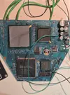
First i decided to just set up the video part to check if everything works as it should since i dont have the power module set up to do the trim. Soldered Hsync/Vsync to the IC directly and the RGB and Composite to solder spots where the connector was, and...

Right off the bat ran into problems:
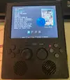
the video came out green and in the wrong place.
20250623_164358.jpg

The green issue was just a setting in the PS2 settings menu. Changed it to RGB from YPbPr.
20250623_200733.jpg

But the off center issue remained. I connected the composite line to the board to check if it has issues also.
20250623_200840.jpg

It did not. Next thing i decided was to check shorts with the soldering but had little faith in that and it didnt seem to be the problem so the next thing to check was the signal of Vsync/Hsync.
Checked Vsync at the IC ant at the end of the wire on the screen board. Then did the same with the Hsync. Signals were the same, no voltage drop or what ever.
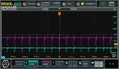
So then i checked the timing of the signals, and... they are off
RigolDS1.png

RigolDS9.png

Since the Hsync and Green ar in sync with each other it seems that the Vsync is off. I have no idea what to do with this. I have checked that no capacitors or resistors unsoldered.
Probing more with the oscilloscope it seemed like Vsync was jumping around one measurement ir was inline with Hsync and RGB other time it wasnt. The composite signal looks fine.
So im up for suggestions. Next thing im gonna try is take my 77k ps2 ant look at its video IC and signals it sends out.
 
Also i should mention i have tried aligning the screen through the screen menu. Up/down is possible, but left/right at max settings is still a little off screen. And other thing is this distortion at the bottom of the screen.
1750738936592.png
 
Some more info:
RigolDS7a.png

I connected Vsync/Hsyn/Blue/Composite to the oscilloscope. By the looks it seems like signal is the same. Where composite white signal begins blue signal begins. So maybe its the Screen control board i have a second one i will test it out today.
COMP.jpg

VGA.jpg

This is manual left/right screen positioning at a maximum. Its still off.
And another issue is the picture is jittery.
ezgif-35908b0d6f9561.gif
 
Update. In general VGA seems to only work in specific screens where you can manually change the signal to VGA, but those settings only works on those screens and once you start the game it reverts back into native PS2 signals that are not typical VGA signals.
Step one File.jpg

Go to wlauncher elf and go to screen settings
Step two File.jpg

Step three File.jpg

Step four File.jpg

Change this bad boi to VGA and the picture becomes perfect. It fills up the whole screen, there is no shaking and no artifacts.
Step five File.jpg

Then go to OPL
Step one OPL.jpg

Go to menu and then display settings
Step two OPL.jpg

Change Video mode to the one in the picture and the hit ok. Same as before, no artifacts left, no jittering, and full screen filled up.
Step three OPL.jpg

Now this is not really a solution since it only affects these speciffic screens. But when you get back to the original screen that shows up when you boot the PS2 or start a game its still all jittery with artifacts and the PS2 signal being sent out is not really properly set up for the screen. What i understand now is that both VGA and Composite signals are synchronized the same, but the issue seems to be that the screen is not responding to them correctly, or maybe its some different syncs used for PS2 than the ones that the screen is waiting for.

These are Vsync(yellow) and Hsync(blue) from the boot screen that is jittery and stuff
RigolDSded0.png

RigolDSded1.png

And these are Vsync and Hsync from the OPL screen after the setting change
RigolDSsfc0.png
RigolDSded3.png
 
Last edited:
yes the boredom that the signal must be accepted by screens that support 15khz if I'm not mistaken, games like outrun 2006 that have the choice of progressive scan the image quality is exceptional
 
its been a while (building a house and a campervan at the same time) but im back on the project. I immediately ran into problems.
After the advanced trim the board does not boot. I have checked under a microscope to look if there are any shorts after the sanding before powering it up, there arent any. Pic related.
1764344977542.webp


Measured the voltages (GND of the motherboard) ant the voltages at the solder points and got this result.
5v-4.99
3.5v-3.465
1.25V - 1.223
2.5v - 2.47
1.8v - 1.77
Maybe the voltages are not close enough.
ive used this board for power and powered it from a lifepo4 2s

b046f5fb-64ee-412c-8bc2-e042114a0c84.webp

80ce7af7-f371-4ae0-be50-1bb15d7c7c41.webp

The main IC's get warm as if they are running but 'ON' button does nothing. help needed.

Other thing that ive done is made a schematic for the controller
1764345866252.webp

1764345926239.webp

Some of the notations are in my native tounge, but i thing its not too difficult to understand the schematic.
 

Attachments

  • 80ce7af7-f371-4ae0-be50-1bb15d7c7c41.webp
    80ce7af7-f371-4ae0-be50-1bb15d7c7c41.webp
    502.9 KB · Views: 34
So figured out the issue ( probably ). I looked and looked at the motherboard and didnt see what could be wrong, but decided that i somehow damaged the board and its fried. I saw that coming so i bought two 79xxx ps2 i trimmed the second board, and surprise surprise it didnt work either. I thought that i trimmed everything carefully and checked all the edges for shorts with a microscope so i decided that both boards has to be fine and something else must be wrong.
Remade the voltage regulator board, thought it might be something wrong with it. It wasnt. But i noticed that the board remains cool, and after i ground the power on pin it warms up, so i decided that the motherboard works fine. i started to test for video signal on the oscilloscope.
And it seems that my issue was using to thin and long of a wire for composite and to add to that i found out that if i test at the red circle the composite signal is significantly stronger than where i soldered the wire to which is the yellow circle.
CompositeTst.webp
rigolds0-webp.40886


so both motherboards do work.
c0eb555b-12de-48e2-9a92-a5e92e64ec26.webp


other thing i did was a shitty controller pcb to test if everything is fine with my schematic, before ordering it from JLC. And it wasnt. First of i didnt have large enough pcb to make the full controller so the R1 R2 L1 L2 didint fit:d
I65zdinta Ps2 kont pcb.webp
eszdinimo procese.webp


The first actual issue was that when i connected the controller to ps2 it didnt register. And what had happened is during soldering i mixed up the polarity of the zener diodes.
ZenerDiode.webp

I reversed it back and then it started working. Just for my own interest i reversed the other one to see what happens. The ps2 shows that a controller is connected but the buttons are not recognized. So if one is reversed ps2 does not recognize the controller if the other is reversed it recognizes the controller but not the buttons them selves.
https://store.curiousinventor.com/guides/PS2 this helped to put me on track since it says here that ACK and MISO should be pulled to high, but original controller boards does not do that but they do have zener diodes to ground.


Another issue was Analog/Select/Start buttons. It was my own fault again, i did the schematic wrong. They need to get 3.3v directly as opposed to other buttons that have to go through a resistor.
kontrolerio schema v2.webp


And the third issue was that the Joystick signals were reversed, when i push the analog stick up it registers as down. That happened because i downloaded a joystick component for altium and just connected the way it was shown. In reality all the polarities should be the other way around.

Testing it out.webp
 

Attachments

  • RigolDS0.webp
    RigolDS0.webp
    51.7 KB · Views: 59
Last edited:
Not much progress over these few days. Been working on the shape of the case, decided to go for controller on the bottom rather than sides. Also tried out the smaller Joysticks but i dont like the feel. I like them chunky boys so i will be using the original sized analogs but with xbox360 caps.
bd992437-8bef-42d1-a1de-6fe35b671401.webp
df4c6804-c315-4675-bc47-d0690c961d0d.webp

Rough draft of my idea

Another thing i did was connected the FMCB memory card to the motherboard for a test.


MemCard.webp
778fd332-d03f-48e9-ab6a-789e76ebc59b.webp


Also remembered i had an old laptop i havent used in like 6 years, so took the speakers out of it.

61b5f2b3-88c7-48cc-b84a-065207fd1cf1.webp
Spk3.webp
Spkr1.webp
SPKRS.webp


havent solved the power management yet but decided i will try to make a single pcb that includes type-c charging with 2s BMS and the different volts needed. Since im not only doing this for myself but also as a bachelors project i need more pcbs made by myself.
 
Last edited:
Minor update. Have been working out the pcb's and the form of the system. Today ill be ordering the controller pcb, audio/microSD pcb and a PMS that is a modified @Legend board with charging from 5v. Im not posting the pcbs yet, because i have not tested them yet. But once i know that they work i will post the schematics and gerbers here.

More updates soon.

1765741723171.webp
 
So a bit of an update. Finalising the form of the PS2P. Quite a few test prints.
a5180c55-ec7a-4df8-bc64-936c86547f0a.webp

But its almost done.
c61f58d1-6967-4923-be9f-94ba06c6b967.webp
You can see the heatsink, to the left of it there is a ventilator thats under the plastic. It draws air through the right of the wall, air goes through the heatsink and then out the back. But i will do an in depth once everything is finished.
Tested out the controller boards, every thing is fine, except R1 and R2, its mixed up, because i made a mistake when tracing back the original controller, and when i did the test print i couldnt fit R1 R2 so i didnt catch it in time:d But will post a fixed schematic in the end.
56ae3759-0227-4271-9be1-ffd0e3f96501.webp

other issue is a dumb one...
b2d86701-66aa-4086-9683-b50b541e710b.webp

The analogs touch... its basically at max when they do, but i dont have the time now to order new PCB and remake the 3d model, so for now this will do.
As for the PMS ive soldered everything, i get the correct voltages, tested it out on the PS2 mother board it starts up and boots into the FMCB.
382c5ef2-ce0d-4dde-b27c-6ee8ae1e60e9.webp

But i havent yet tested out the charging protection. In essence using the flat packs that i use, you could connect them directly since they have BMS's on them, but think i will just use the one that i integrated on the board, plus if someone would want to use the board with the 18650 they could.
1bcf90f8-dc67-48d4-8f19-5421e8cf800a.webp


More updates in a couple of days
a9cf478e-40f2-4a9d-9190-1518fdcb47c6.webp
 
Been griding as MF :D
Its almost done.
For now i have printed the case with the Elegoo Carbon Centauri from PETG, and the buttons with Elegoo Saturn 4 Ultra from ABS like resin.
But im going to reprint the case from resin too, i think im going to paint the buttons purple, the case itself is going to be painted black but im going to splash some purple paint on it might look cool, will see.
Screenshot 2025-12-30 223603.webp

I also managed to fry one PS2 motherboard, during moving from one case to another i probably shorted something, and it wasnt turning on, started to probe around and found out i have a short on the motherboard from 1.8V to ground. Then also started probing my PMS and found that it was fired too, you can see a 1.8V trace fired off near yellow/green wire solder pad.
Another thing with the PMS, the 5V, i dont like it, it needs to be recalculated i think, it gives 5V but its noisy and it seems its interfering with the screen a little. And i think i calculated something wrong since the datasheet says its switching freq should be around 600kHz but its only 90(blue) while the screens original 5V is 322kHz(yellow)
20251227_200314.webp
RigolDSvid.3.webp
5V.webp

Also tried out my pcb for the microSD and sound. Works fine. i couldnt find an amp IC with integrated vol control buttons that would arrive in time for my project so i made do with what i could find. Its a PAM8603 amp then the smaller one is a MCP41050 digital potentiometer that is controlled through SPI from AtMega328P(a bit of an overkill, but i had like 20 of them laying around so went with it) and Vol+ Vol- Mute buttons. But i will probably change the code later on, since i wrote the code so that when it boots it goes to the middle of the volume, and its a little to loud. Another thing i made is that one button press changes the volume by 1/255 and you can hold the button to lower or increase the volume but it takes to long, will probably rewrite the code so one press is like 20/255 increment. Also yes i know there are smaller crystals but also had that one laying around:D
20251228_222743.webp

Rest of the photos are just random, but soon will do a final post with the final result and shcematics and gerbers
20251229_202504.webp
20251228_172212.webp
20251225_111210.webp
Screenshot 2025-12-30 223225.webp
Screenshot 2025-12-30 223328.webp
 

Attachments

  • 1767126995376.webp
    1767126995376.webp
    26.4 KB · Views: 23
Last edited:
Back
Top